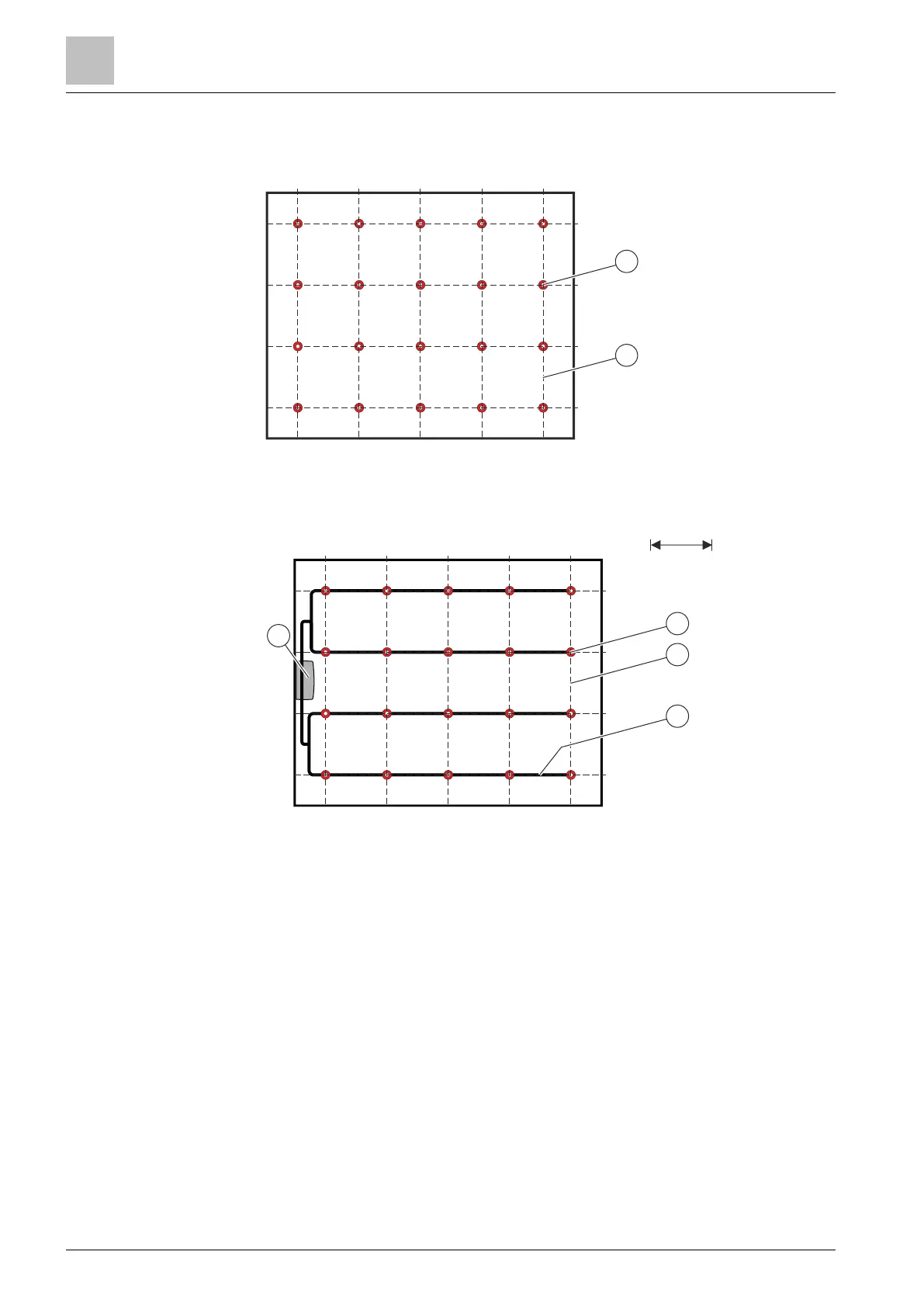
4.6 Monitoring area grid
1. Place a grid(2) showing the aspirating holes(1) over the monitoring area.
Fig. 13: Deciding on the locations of the aspirating holes
2. Decide on the locations and topology of the pipes.
2.52.5 5 5 5 5
2.5
2.5
5
5
5
1
3
4
2
5 m
Fig. 14: Deciding on the topology of the pipes
1 Aspirating hole
2 Grid
3 Pipe
4 Aspirating smoke detector
Planning
Monitoring area grid
4
30 | 48 A6V11783979_en--_a
 Loading...