Technical Instructions
LME-1000
LME Series
Lockout
Blower On
Prepurge (Note 2)
Trial for Ignition
Flame Detection
Safety Time 2
Operation
Drive to Low Fire
Shutdown
Postpurge (Note
2)
Home Run
Evacuate
Atmospheric Test
Fill
Pressure Test
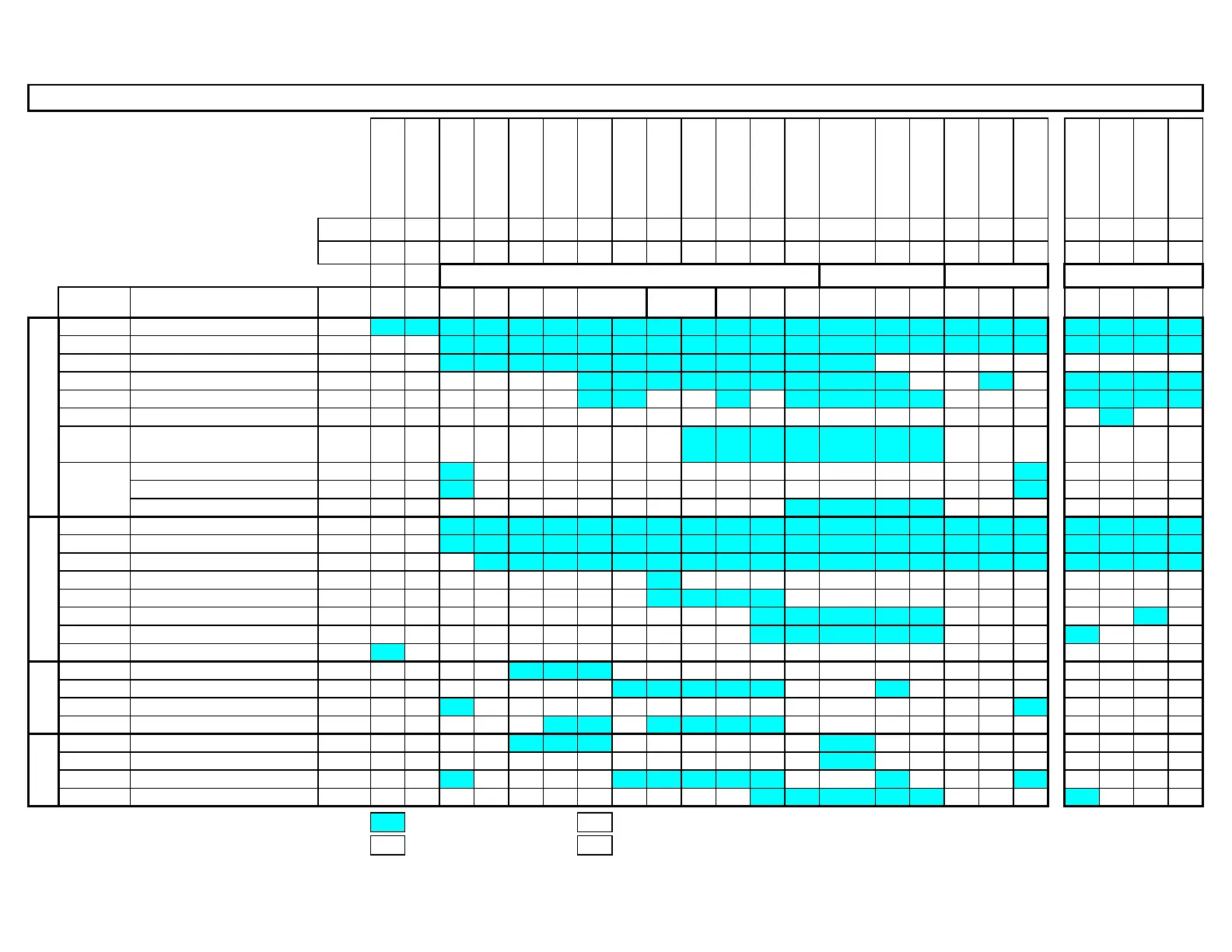
Phase LOC OFF 21 22 24 22 30 36 40 42 44 50 52 oP oP1 70 72 74 10 80 81 82 83
Param. 259 225 260 257 230 231 232 240 212 234 242 243 244 245
Terminal Description Notes
X3-04.5 Main Voltage
X3-04.1 Safety Loop X X
X5-03.1 Burner On M
X3-02.1 Air Pressure Switch Note 3 X M
X5-01.2 Gas Pressure Switch(es) Note 4
X9-04.2 Valve Proving Pressure Switch X
POC (P237.00 = 1, P237.01 = 0)
POC (P237.00 = 2, P237.01 = 0) X
High Gas Press. Sw. (P237.01 = 1)
X2-02.3 POC Source X X
X6-03.3 Safety Valve X X
X2-01.3 Blower X X X
X4-02.3 Ignition Transformer X X X X X X X X X X X X X X X X X X X X X X
X7-01.3 Pilot Valve Note 1 X X X X X X X X X X X X X X X X X X X
X7-04.4 Main Valve V1 Note 1 X X X X X X X X X X X X X X X X X
X7-02.3 Main Valve V2 X X X X X X X X X X X X X X X X X
X2-03.3 Alarm X X X X X X X X X X X X X X X X X X X X X X
X2-09.3 Drive to High Fire X X X X X X X X X X X X X X X X X X X
X2-09.2 Drive to Ignition / Low Fire X X X X X X X X X X X X X X X X
X2-09.1 Drive Closed X X X X X X X X X X X X X X X X X X X X X
X2-09.4 Position Feedback M M M M M
CR-1 Drive to High Fire X X X X X X X X X X X X X X X X X X X
CR-2 Release to Modulate X X X X X X X X X X X X X X X X X X X X X X
CR-3 Drive to Low Fire X X X X X X X X X X X X X X X
CR-4 Main Valve V2 Note 1 X X X X X X X X X X X X X X X X X
Legend :
Energized X De-energized
Energized or de-energized M
Must be energized by end of phase
RELAYS INPUTS
X2-02.4
ACTUATOR
Flame Signal
OUTPUTS
SHUTDOWNSTARTUP VALVE PROVINGOPERATION
X
X10-05.1
X10-06.2
X
PME75.811A1 Phase Diagram with Relays
X
SAFETY
TIME 1
Appendix A Page 12 SCC Inc.

 Loading...
