MC45 Hardware Interface Description
P R E L I M I N A R Y
MC45_HD_01_V00.02a Page 21 of 90 12.08.2002
2.2 Circuit concept
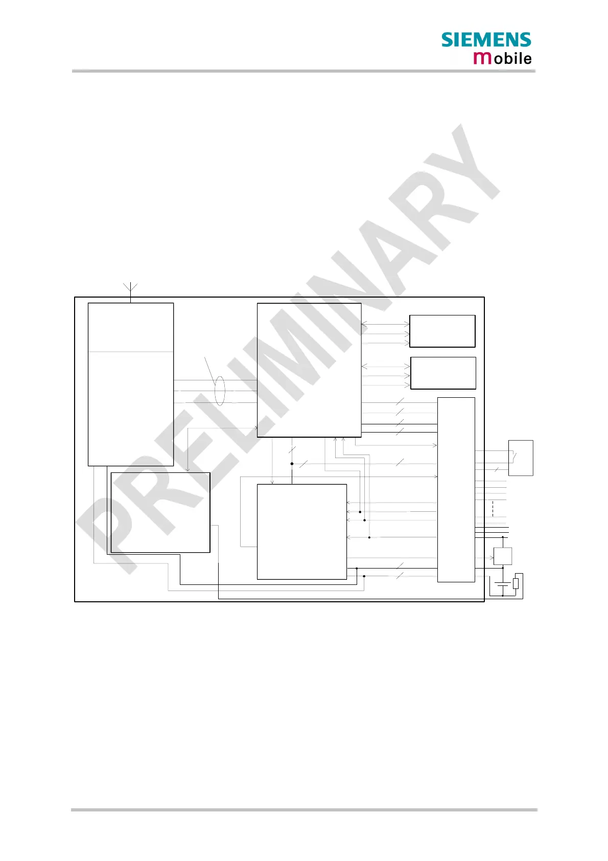
Figure 1 shows a block diagram of the MC45 module and illustrates the major functional
components:
· GSM / GPRS baseband processor
· Power supply ASIC
· Flash
· SRAM
· GSM RF section incl. transceiver and RF power amplifier
· Antenna interface
· Application interface (board-to-board connector)
GSM Controller
Power
Supply
ASIC
SIM
BATT+
GND
IGT
EMERGOFF
RS232(1)
RS232(0)
5
2x Audio
SIM Interface
CCRST
CCCLK
CCIO
CCIN
(GND)
Data
Adr
Control
Receive
Send
Control
MC45
Interface
RF - Baseband
5
5
Measuring
Network
4
CCIN
CCVCC
POWER
BATT_TEMP
VDDLP
SYNC
VDD
RF Part
RF Power
Amplifier
Data
Adr
Control
SRAM
Flash
CHARGE
6
8
9
DAI
5
4
6
POWER
+
Ext.
Charging
Circuit
NTC
Application Interface
(50 pins)
Figure 1: MC45 block diagram