MC45 Hardware Interface Description
P R E L I M I N A R Y
MC45_HD_01_V00.02a Page 65 of 90 12.08.2002
4 Antenna interface (antenna reference point – ARP)
To suit the physical design of individual applications MC45 offers two alternative approaches
to connecting the antenna:
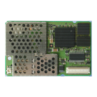
The standard layout of MC45 comprises an antenna connector from Hirose assembled on
the component side of the PCB (top view on MC45) plus a antenna pad placed on the
bottom side. Both solutions can only be applied alternatively: Whenever an antenna is
plugged to the Hirose connector, the pad must not be used. Vice versa, if the antenna is
soldered to the pad, then the Hirose connector must be left empty.
Both RF interfaces have an impedance of 50". MC45 is capable of sustaining a total
mismatch at the antenna connector or pad without any damage, even when transmitting at
maximum RF power.
To help you choose an appropriate antenna, Chapters 5.4 and 8 provide technical
specifications and ordering information. The external antenna must be matched properly to
achieve best performance regarding radiated power, DC-power consumption and harmonic
suppression. Matching networks are not included on the MC45 PCB and should be placed in
the host application.
Regarding the return loss MC45 provides the following values:
Table 20: Return loss
State of module Return loss of module Recommended return loss of application
Receive > 8dB > 12dB
Transmit not applicable > 12dB
Idle < 5dB not applicable