MC45 Hardware Interface Description
P R E L I M I N A R Y
MC45_HD_01_V00.02a Page 75 of 90 12.08.2002
Table 25: Ordering information for Hirose U.FL Series
Item Part number HRS number
Connector on MC45 U.FL-R-SMT CL331-0471-0-10
Right-angle plug shell for
Æ 0.81 mm cable
U.FL-LP-040 CL331-0451-2
Right-angle plug for
Æ 0.81 mm cable
U.FL-LP(V)-040 (01) CL331-053-8-01
Right-angle plug for
Æ 1.13 mm cable
U.FL-LP-066 CL331-0452-5
Right-angle plug for
Æ 1.32 mm cable
U.FL-LP-066 CL331-0452-5
Extraction jig E.FL-LP-N CL331-04441-9
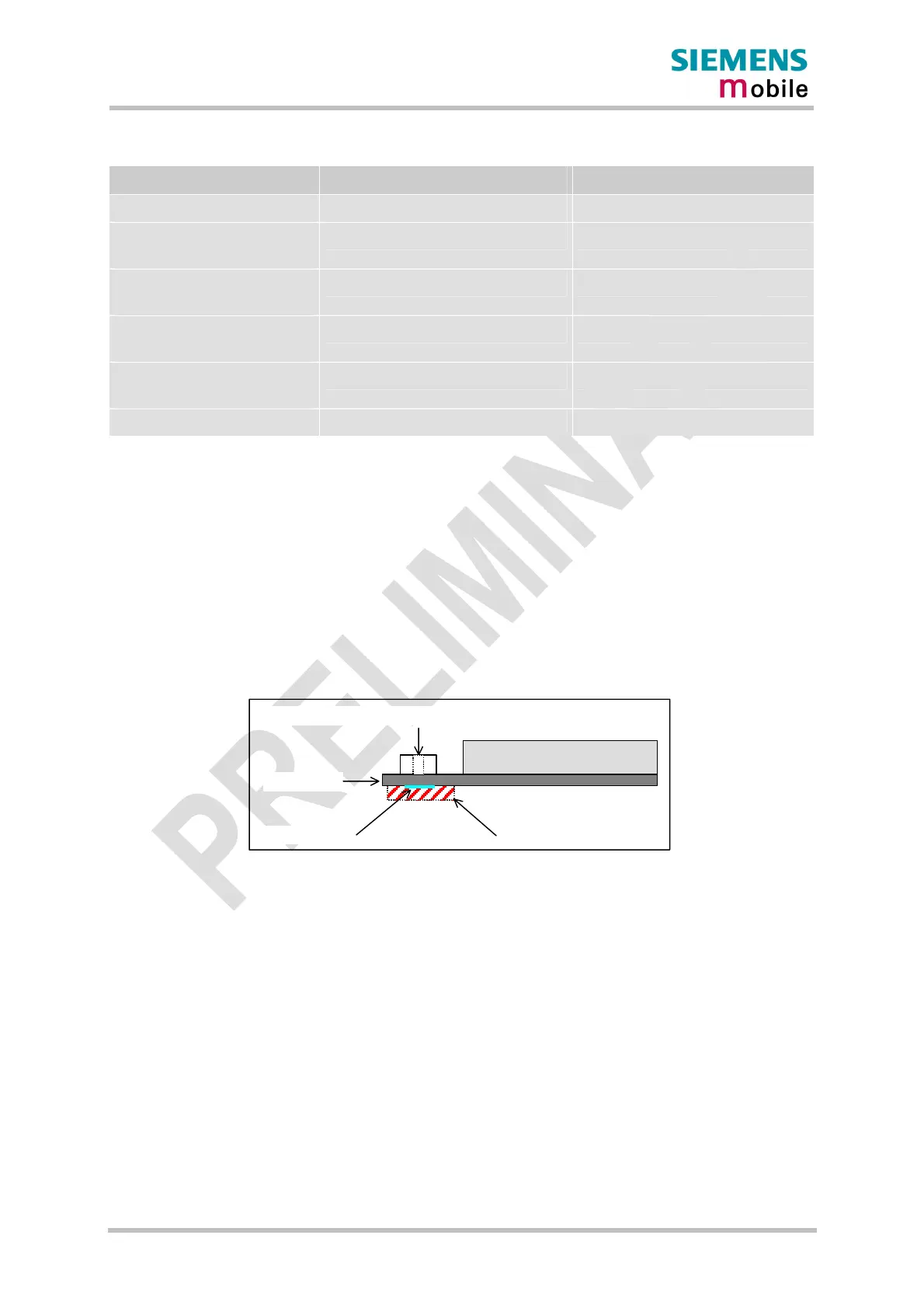
5.4.2 Antenna pad
The antenna pad on the bottom of the MC45 PCB must not come into contact with the
holding device or any other components of the host application. The pad must be a
surrounded by a restricted area filled with air, which must also be reserved 0.8 mm in height.
MC45 PCB
Hirose antenna connector
RF section
Antenna pad
Restricted area
Figure 37: Restricted area around antenna pad