MC45 Hardware Interface Description
P R E L I M I N A R Y
MC45_HD_01_V00.02a Page 33 of 90 12.08.2002
3.3 Power up / down scenarios
3.3.1 Turn on MC45
MC45 can be activated in a variety of ways, which are described in the following chapters:
· via ignition line /IGT: starts normal operating state (see Chapters 3.3.1.1 and 3.3.1.2)
· via POWER line: starts charging algorithm (see Chapters 3.2.3.4 and 3.3.1.3)
· via RTC interrupt: starts Alarm mode (see Chapter 3.3.1.4)
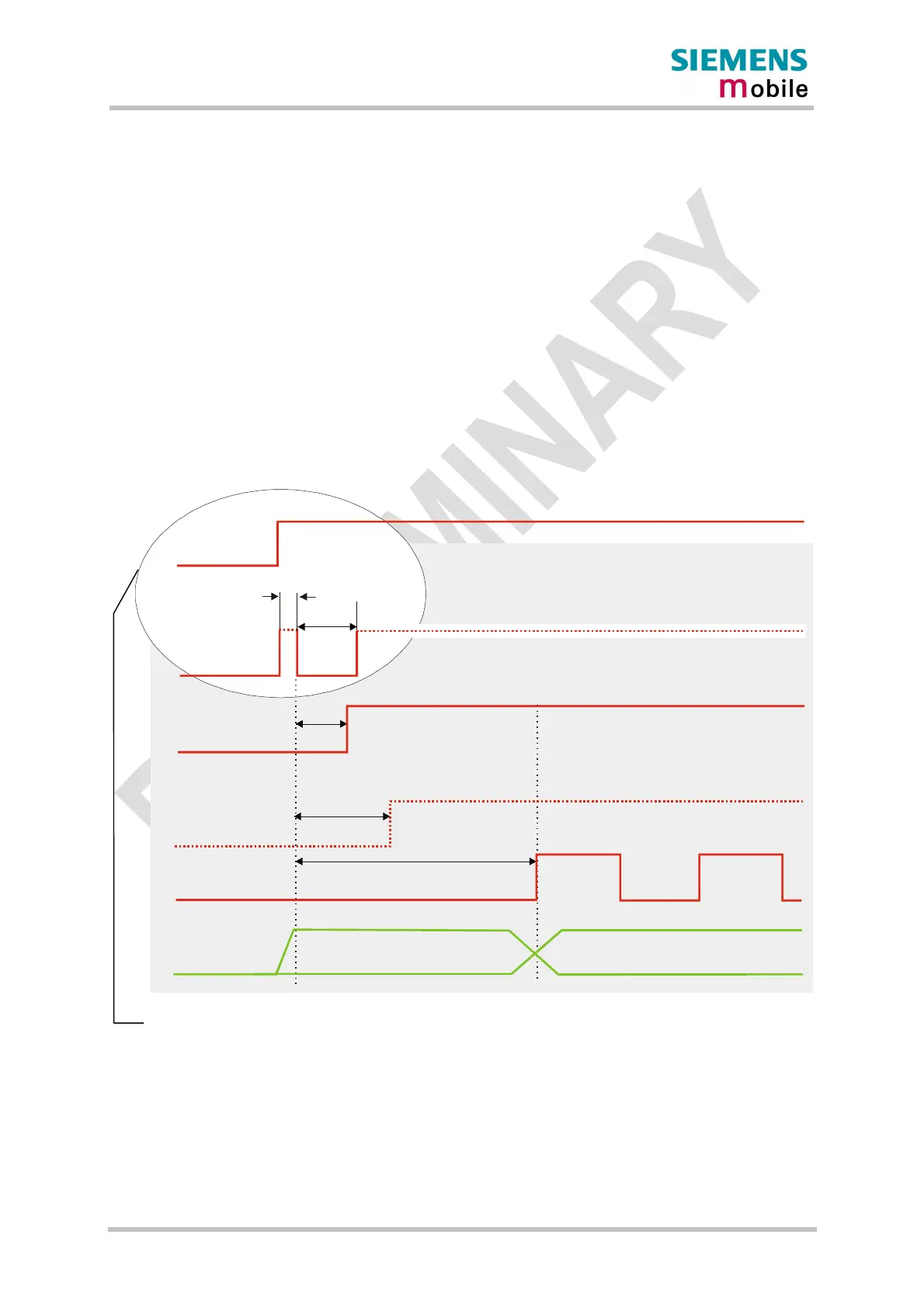
3.3.1.1 Turn on MC45 using the ignition line /IGT (Power on)
To switch on MC45 the /IGT (Ignition) signal needs to be driven to ground level for at least
100ms. This can be accomplished using an open drain/collector driver in order to avoid
current flowing into this pin.
Internal reset
ca. 180ms
generated by GSM engine
/EMERGOFF
max. 900ms
RS-232
interface
undefined
defined
VDD
50 to
100ms
BATT+
/IGT
min. 10ms
min.
100ms
HiZ
HiZ
Figure 6: Power-on by ignition signal
If configured to a fix baud rate, MC45 will send the result code ^SYSSTART to indicate that it
is ready to operate. This result code does not appear when autobauding is active. See
Chapter AT+IPR in [1].
In a battery operated MC45 application, the duration of the /IGT signal must be 1s minimum
when the charger is connected and you may want to go from charging to Normal mode.
For details please see Chapter 3.3.1.2