MC45 Hardware Interface Description
P R E L I M I N A R Y
MC45_HD_01_V00.02a Page 47 of 90 12.08.2002
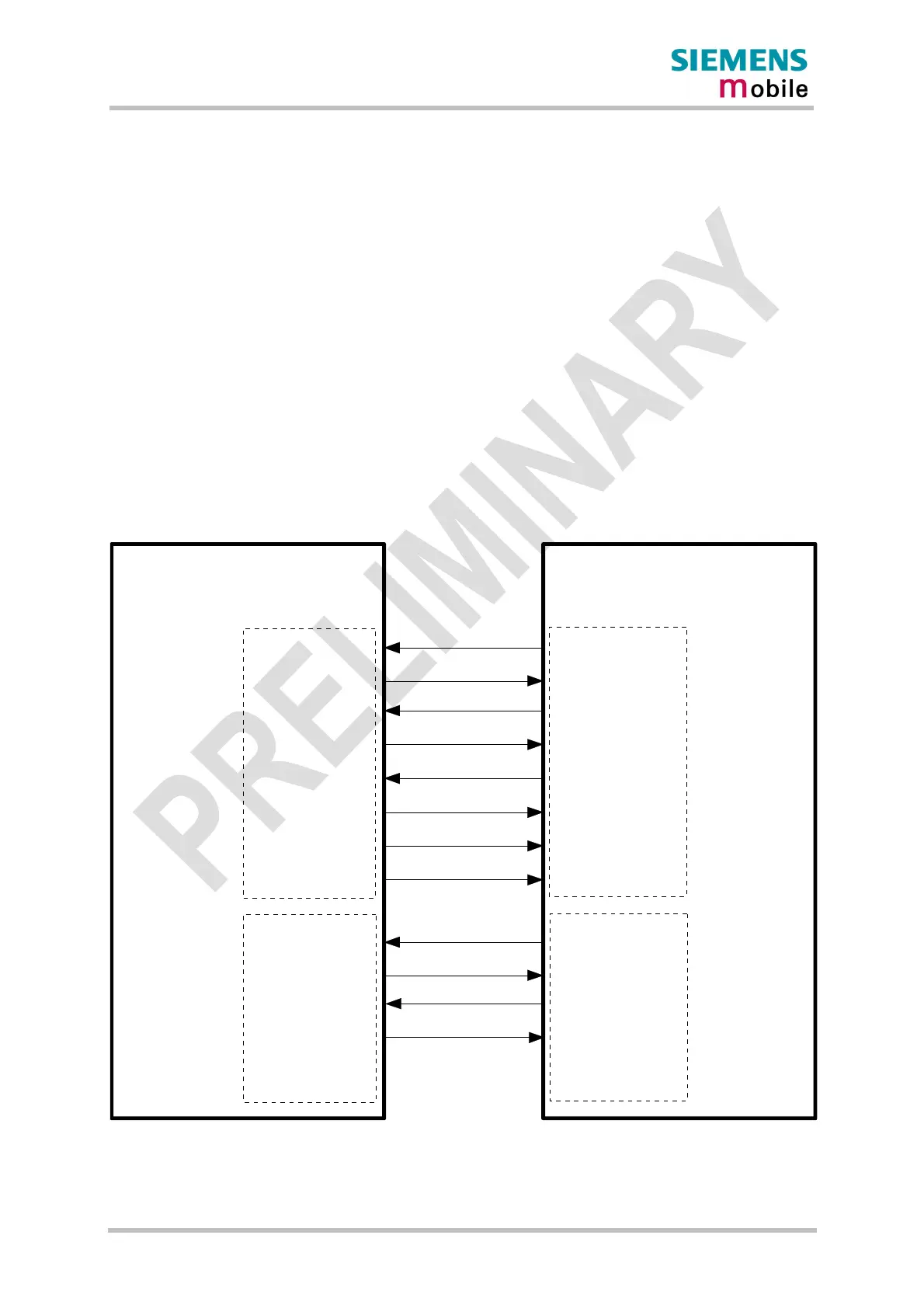
3.5 Serial interfaces
MC45 offers two serial interfaces, each operating at 2.65V level. All RS-232 signals on the
board-to-board connector are low active. Both interfaces are implemented as a serial
asynchronous transmitter and receiver conforming to ITU-T RS-232 Interchange Circuits
DCE.
The GSM engine is designed for use as a DCE. Based on the conventions for DCE-DTE
connections it communicates with the customer application (DTE) using the following
signals:
RS-232(0)
· Port /TXD @ application sends data to the module’s /TXD0 signal line
· Port /RXD @ application receives data from the module’s /RXD0 signal line
RS-232(1)
· Port /TXD1 @ application sends data to module’s /TXD1 signal line
· Port /RXD1 @ application receives data from the module’s /RXD1 signal line
MC45
Application
/TXD
/RXD
/RTS
/CTS
/RING
/DCD
/DSR
/DTR
/TXD1
/RXD1
/RTS1
/CTS1
RS-232(0) interface
(DTE)
(DCE)
RS-232(1) interface
RS-232(0) interface
RS-232(1) interface
/TXD0
/RXD0
/RTS0
/CTS0
/RING0
/DCD0
/DSR0
/DTR0
/TXD1
/RXD1
/RTS1
/CTS1
Figure 15: RS-232 interfaces