ECO REFERENCE MANUAL
13-10
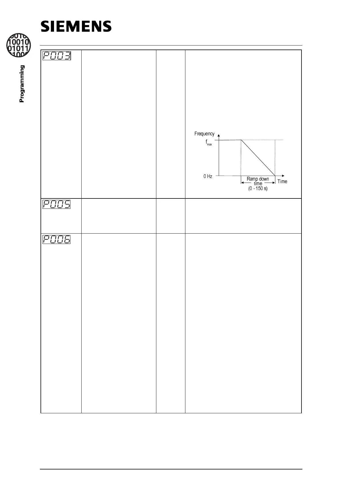
Ramp-down time 0-2
[0]
This is the time taken for the motor to
decelerate from maximum frequency to
standstill. The maximum frequency is set by
parameter P013. Setting the ramp-down
time too short can cause the inverter to trip
(Fault code F001 = DC link overvoltage).
This is also the period for which injection
braking is applied, if selected (refer to
parameter P073 in Expert mode).
Digital frequency setpoint
(Hz)
0 - 150.0
[50]
(60)North
America
Sets the frequency that the inverter will run
at when operated in digital mode. Only
effective if P006 = 0 or 3.
Frequency setpoint source
selection
0-2
[0]
The value of this parameter 0, 1or 2) selects
the mode of control of the inverter’s
frequency setpoint.
0 = Digital motorised potentiometer
(Keypad control potentiometer).
The inverter runs at the frequency set in
P005 (refer to Expert mode) and can be
controlled with the [
up
] and [
down
] keys. If
P007 (see below) is set to 0, the frequency
can be increased or decreased by setting
any two of the digital inputs (P051 to P055
or P356 - refer to Expert mode) to the
values of 11 and 12.
1 = Analogue. The inverter output
frequency is controlled by analogue input
signals (0-10V, 0/4-20mA or potentiometer).
2 = Fixed frequency. Fixed
frequency is only selected by setting the
value of at least one of the digital inputs
(P051 to P055 or P536 - refer to Expert
mode) to the value of 6 or 18.
)UHTXHQF\
I
PD[
+]
7LPH
5DPS GRZQ
WLPH
V
 Loading...