ECO REFERENCE MANUAL
15-28
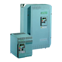
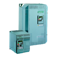
OUTPUT REACTORS (CHOKES)
Output reactors are fitted to the output terminals (U, V & W) of the inverter to allow operation with long
motor cables. The inductance of the output reactor compensates for the stay phase-to-phase and
phase-to-earth capacitance of the motor cable.
As the motor cable length is increased the total stray capacitance of the motor cable also increases.
This stray cable capacitance combined with the residual voltage spikes on the inverter output (caused
by the Pulse Wide Modulation (PWM) switching of the inverter’s IGBT output devices) has the effect of
causing current spikes to flow back to the inverter. These current spikes may cause nuisance tripping
of the inverter which can be prevented by the installation of an output reactor.
The recommended motor cable lengths for screened and unscreened cables when output reactors are
fitted are shown within the table below:
Maximum Cable Length (m)
for MICROMASTER Eco & MIDIMASTER Eco
Inverter
Rating
(kW)
Standard (no output
reactor fitted)
Output Reactor
Fitted
Output Reactor
Fitted
Screened
Cable
Unscreened
Cable
Screened Cable Unscreened Cable
One
Reactor
Fitted
Two Reactors
Fitted in
Series
One
Reactor
Fitted
Two
Reactors
Fitted in
Series
Up to 1.5kW 80 110 150 200 180 250
2.2 to 3 135 165 200 250 250 300
4 200 200 250 300 300 350
5.5 200 200 250 300 300 350
7.5 200 200 250 300 300 350
11* 50 50 100 150 150 200
15* 50 50 100 150 150 200
18.5* 50 50 100 150 150 200
22* 50 50 100 150 150 200
30* 50 50 100 150 150 200
37* 50 50 100 150 150 200
45* 50 50 100 150 150 200
55 300 300 300 400 400 500
75 300 300 300 400 400 500
90 200 300 300 400 400 500
 Loading...