PAD-5-MB when programming the address, because it will get the same address as
the PAD-5-MB. Program the expansion module apart from the PAD-5-MB. The DPU
programs the address of the PAD-5-MB, since the PAD-5-MB is considered a loop
device. See DPU programming section for more details.
9. Next, install the batteries (7AH and 18AH fit inside the 1HU enclosure, up to 35Ah
batteries can be installed in the 2HU enclosure). Use the provided battery cable
assembly that comes with the PAD-5-MB to connect the batteries.
10. For Seismic applications, the maximum battery size for both enclosures is 18Ah
and requires the use of the Battery Bracket FHA2032-U1 (P/N S54430-B43-
A1). In order to use larger batteries, a separate battery box CAB-BATT (P/N
500-633917) black, or (P/N 500-634925) red, must be used.
NOTE → Remember, connect the power supply to X100 first, then connect the batteries
to X101. When servicing the panel, the order is opposite. Disconnect the
batteries, then the power supply.
2.2 DPU programming PAD-5-MB and expansion card
address
1. The P2 circuit is powered by the XDLC.
The PAD-5-MB, PAD-5-CLSA or PAD-5-CDC, must not be connected to
connector X700. The address needs to be programmed prior to connection to
the XDLC. Also, if using expansion boards, they must not be connected to the
PAD-5-MB, or the address will be duplicated on both boards.
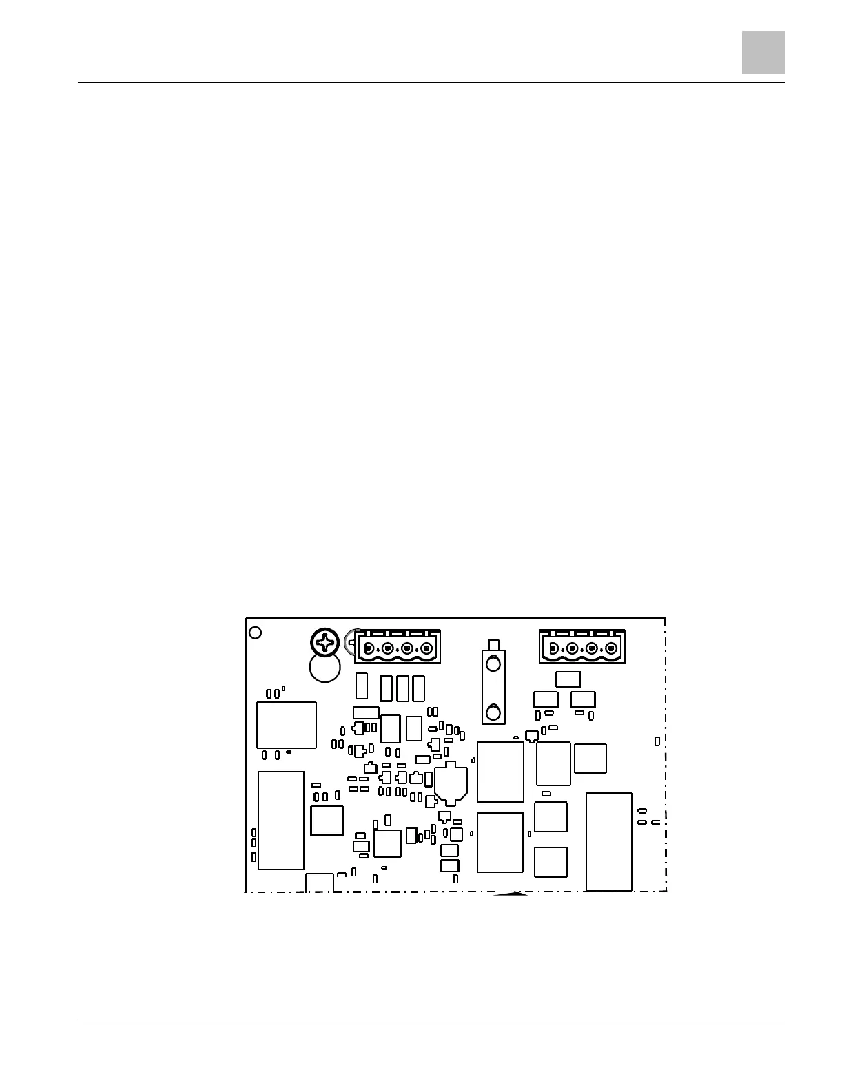
2. All the boards have an outline on the DPU programming holes, which indicate
polarity. Make sure the DPU programming cable is connected so “ + “ is
oriented correctly (see Figure 4a).
 Loading...


