Wiring and Configuring the PAD-5-MB
There is only one connection allowed from Terminals 1 and 2. Terminals 3 and 4
allow for tapping the output to another device. Any fault on any X800 terminals will
affect all connected devices. Terminals 1/3 and 2/4 are tied together internally.
3.2.3.2 X800 Auxiliary output terminal block
Positive feed for Aux circuit (DC +24 V)
Admissible cable cross-section: 1 x 12-18 AWG or 2 x 16-18 AWG
3.2.4 FDNet (P2) Wiring and Topologies
The P2 Interface is the connection between the fire control panel and the PAD-5
Main board. An isolator feature used to disconnect the outgoing FDnet from the
main board if a short circuit is detected on the part of the FDnet. Due to the
configuration of the PAD-5 with option expansion module, there is no polarity
insensitivity, regardless if the expansion module is connected. Only the DPU
programming port for programming the address is polarity insensitive.
3.2.4.1 Wiring X700 FDNet (P2) Input
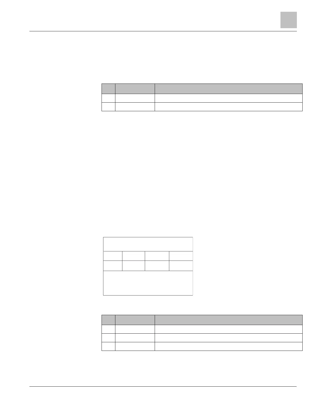
3.2.4.2 X700 FDNet (P2) terminal block
Positive feed for FDNet (P2) IN / OUT
Return feed for FDNet (P2) IN
Return feed for FDNet (P2) OUT
Admissible cable cross-section: 1 x 12-18 AWG or 2 x 16-18 AWG
 Loading...


