Fail-Safe Modules
7.5 4/8 F-DI DC24V PROFIsafe Digital Electronic Module
ET 200S Distributed I/O System - Fail-Safe Modules
120 Installation and Operating Manual, 08/2008, A5E00103686-07
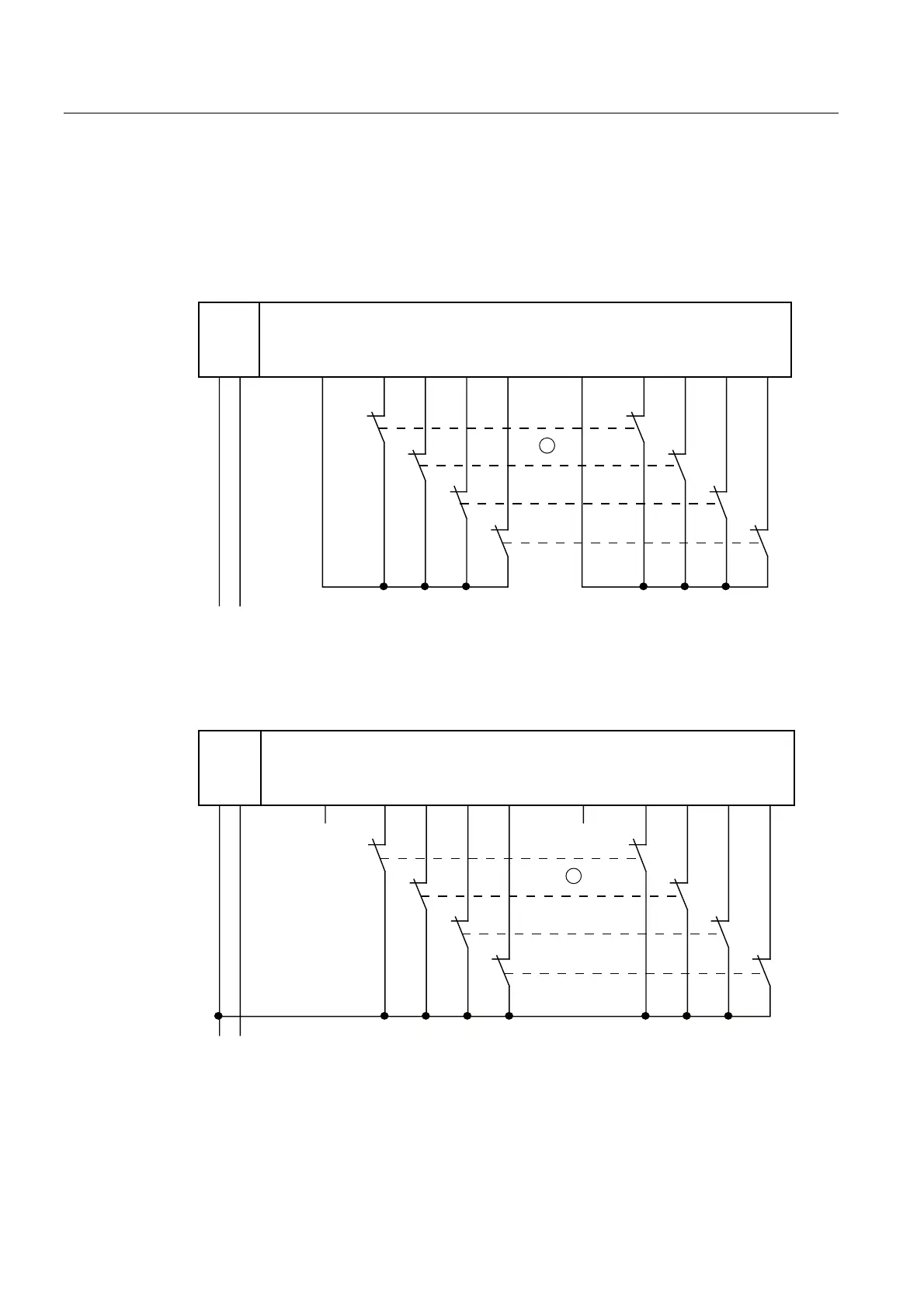
Wiring Diagram for Application 2.2 - Connecting a Two-Channel Sensor to Two Channels
A 2-channel sensor is connected to two inputs of the F-module for each process signal (1oo2
evaluation).
The wiring is carried out on the appropriate terminal module.
)',
/ 0 ', ' , ', ' , ', ', ' , ',9V 9V
/ 0
6
6
6
6
30(
① Encoder contacts are coupled mechanically
Figure 7-23 Wiring diagram EM 4/8 F-DI DC24V - a 2-channel sensor connected via two channels,
internal sensor supply
)',
/0 ',',',', ',',',',9V 9V
/ 0
6
6
6
6
30(
① Encoder contacts are coupled mechanically
Figure 7-24 Wiring diagram EM 4/8 F-DI DC24V - a 2-channel sensor connected via two channels,
external sensor supply
 Loading...
