Fail-Safe Modules
7.6 EM 4 F-DI/3 F-DO DC24V PROFIsafe digital electronic module
ET 200S Distributed I/O System - Fail-Safe Modules
Installation and Operating Manual, 08/2008, A5E00103686-07
149
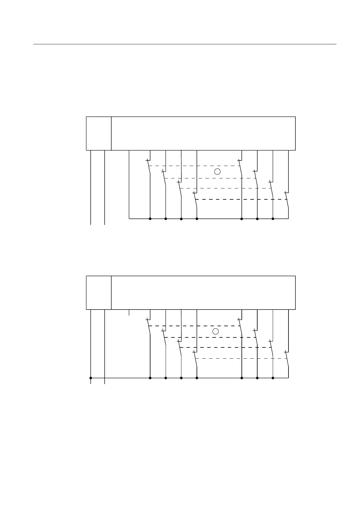
Application 1.2: Wiring diagram for connecting a 2-channel sensor to two channels
A 2-channel sensor is connected to two inputs of the F-module for each process signal (1oo2
evaluation).
The wiring is carried out on the appropriate terminal module.
)',)'2
/ 0
/ 0
96 ',
6
6
6
6
', ', ', ', ', ', ',
① Encoder contacts are coupled mechanically
Figure 7-39 Wiring diagram EM 4 F-DI/3 F-DO DC24V - a 2-channel sensor connected via two
channels, internal sensor supply
30(
)',)'2
/ 0
/ 0
96 ',
6
6
6
6
', ', ', ', ', ', ',
① Encoder contacts are coupled mechanically
Figure 7-40 Wiring diagram EM 4 F-DI/3 F-DO DC24V - a 2-channel sensor connected via two
channels, external sensor supply
 Loading...
