Fail-Safe Modules
7.6 EM 4 F-DI/3 F-DO DC24V PROFIsafe digital electronic module
ET 200S Distributed I/O System - Fail-Safe Modules
150 Installation and Operating Manual, 08/2008, A5E00103686-07
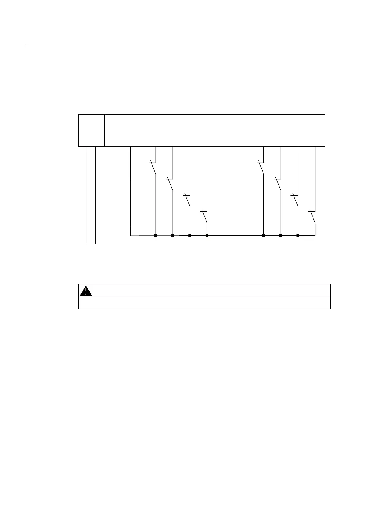
Wiring diagram of the connection of two single-channel sensors to two channels
Two single-channel sensors are connected via two channels to two inputs of the F-module
for each process signal (1oo2 evaluation). The sensors can also be connected to an external
sensor supply.
30(
)',)'2
/ 0
/ 0
96 ',
6
6
6
6
', ', ', ', ', ', ',
Figure 7-41 Wiring diagram EM 4 F-DI/3 F-DO DC24V - two 1-channel sensors connected via two
channels, internal sensor supply
WARNING
To achieve SIL3/Category 3/PLd using this wiring, you must use a suitably qualified sensor.
Assignable Parameters for Application 1.2
Set the "Type of sensor interconnection" parameter to "2-channel equivalent" for the
corresponding input.
You can activate or deactivate the "short-circuit test" parameter. For digital inputs connected
to an external supply, set the "Sensor supply" parameter for the corresponding digital input
to "external". The program will otherwise report a "short circuit" diagnostics event if the
"short-circuit test" is activated.
 Loading...
