Siemens AG SPR8-125.831.01.02.02 POLYMOBIL Plus
05.05 CS PS 24
Inspection and Maintenance 27
Page 27 of 40
Medical Solutions
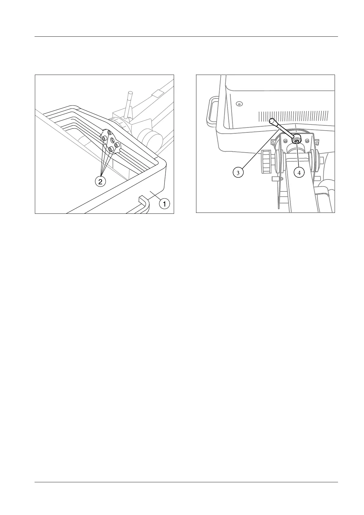
2.6 Single tank
SIM Suspension
• The single tank support (1//Fig. 2 / p. 27) with the single tank must be seated securely
on the flange of the support arm. Check the torque of the 4 screws (2//Fig.2/p.27);
T
• NOM: 25 Nm, Tolerance: ± 10%.
SIM Locking device
• Check the locking handle (3//Fig.3/p.27) for firm seating and tighten, if necessary.
• With the locking device released (locking handle (3//Fig.3/p.27) set counterclock-
wise), it must be possible to move the single tank to all sides easily.
• Checking the locking device: Tighten the locking handle (3//Fig.3/p.27) in clockwise
direction. It should no longer be possible to shift the single tank.
Readjusting the locking device:
- Tighten the locking handle (3//Fig.3/p.27) in clockwise direction up to the stop.
- Unscrew the screw (4//Fig. 3 / p. 27) and push the locking handle off the shaft using
the screwdriver.
- Insert the locking handle in perpendicular position and tighten the screw
(4//Fig. 3 / p. 27) securely.
- Recheck the locking mechanism of the single tank.
Fig. 2:
Fig. 3:

 Loading...