Do you have a question about the Siemens POWERMOBIL and is the answer not in the manual?
Explains emphasized texts like DANGER, WARNING, CAUTION, NOTICE for safety and procedural guidance.
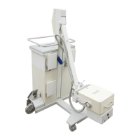
States instructions apply to cable module replacement in POWERMOBIL system and requires 2 persons.
Warns about injuries, requires adherence to system/service manuals and protective conductor test.
Lists required manuals, quick tests, and wiring diagrams for the POWERMOBIL system.
Lists tools and equipment necessary for procedures, referencing the Service Tool Catalogue.
Steps to position the unit, lock brake, use timber, adjust lifting column, and unplug cables.
Instructions for removing basic unit, front C-arm, and horizontal carriage covers, with safety warnings.
Details on disconnecting and removing the X-ray image intensifier and mini voltage supply.
Steps to dismantle DIAMENTOR chamber, remove covers, fan, and cable ties related to POWERPHOS.
Instructions for releasing tension screws, removing clamping pieces, and pulling C-arm cables.
Steps to block cable module, remove cover holders, turn C-arm, and replace cables.
Procedures to remove plates, tape, covers, ferrite cores, and trace cables within the energy chain.
Steps to remove covers, loosen cable clamps, and unscrew cable guides in the horizontal carriage.
Details on detaching cable module, removing nuts, flange, and installing a new flange.
Instructions for unscrewing screws, lifting horizontal carriage, and removing cables from vertical tube.
Steps to place new cable module, lock drums, route cables, and ensure no intersections.
Unscrewing holders, lifting C-arm, and refitting holders to thread cable module into the C-arm.
Inserting cables, attaching clamp block, adjusting toothed belt tension, and securing cables.
Running cables, reinserting POWERPHOS, connecting plugs, attaching clamps, fitting fan assembly.
Connecting Lemosa plug, inserting supply sections, attaching image intensifier, and connecting various cables.
Inserting cables into energy chain, fastening, securing links, attaching ferrite core, connecting inverter.
Securing the front C-arm cover, ensuring cables are not crushed or torn.
Refitting cover plate, reattaching cables, screwing ground wire, reconnecting plugs.
Releasing cable module lock, turning C-arm to align markings, and locking module in position.
Checking sensor adjustment, connecting DMM, adjusting sensor to specific voltage, and retightening.
Rotating the camera and verifying smooth movement and absence of error messages.
Extending/retracting lifting column, checking energy chain movement, and ensuring proper stopping.
Releasing brake, turning C-arm to end positions, checking cable winding, and ensuring no self-movement.
Releasing brake, turning C-arm to angulation end positions, checking cable movement and tension.
Releasing brake, moving horizontal carriage, checking force, and ensuring no self-movement.
Pressing and unlocking the Emergency Stop switch to test functionality.
Checking braking forces/moments as per specific service instructions.
Setting POWERPHOS and collimator according to system service instructions.
Refitting all covers and ensuring protective ground wires make good contact.
Performing the IQ quick test.
Performing protective ground wire test and ensuring resistance is below 0.2 ohms.
| Brand | Siemens |
|---|---|
| Model | POWERMOBIL |
| Category | Medical Equipment |
| Language | English |