12 General
POLYMOBIL Plus SPR8-125.831.01.02.02 Siemens AG
05.05 CS PS 24
Page 12 of 40
Medical Solutions
1.7 Information on the protective conductor resistance test
Observe the information in the “Safety rules for installation and maintenance”
(ARTD-002.731.17...).
The protective conductor resistance is to be measured, documented and evaluated during
maintenance.
NOTE
For evaluation, the value first measured and values documented
during previous maintenance or safety checks are to be compared
to the measured values. A sudden increase of the measured val-
ues, even if the limit value of 0.2 Ohm is not exceeded, indicates
errors in the protective conductor connection (protective conduc-
tor or contacts).
Measurement is to be carried out according to DIN VDE 0751, part 1 (see ARTD part 2).
In doing so, the protective conductor resistance to all conductive and accessible parts is
to be measured in the normal operating status of the unit.
Make sure that control or data cables between components of the unit do not simulate a
protective conductor connection.
During measurement, the power supply cable and additional connection cables with inte-
grated protective conductor are to be moved section by section in order to detect breaks
in the cables.
The protective conductor resistance must not exceed 0.2 Ohm.
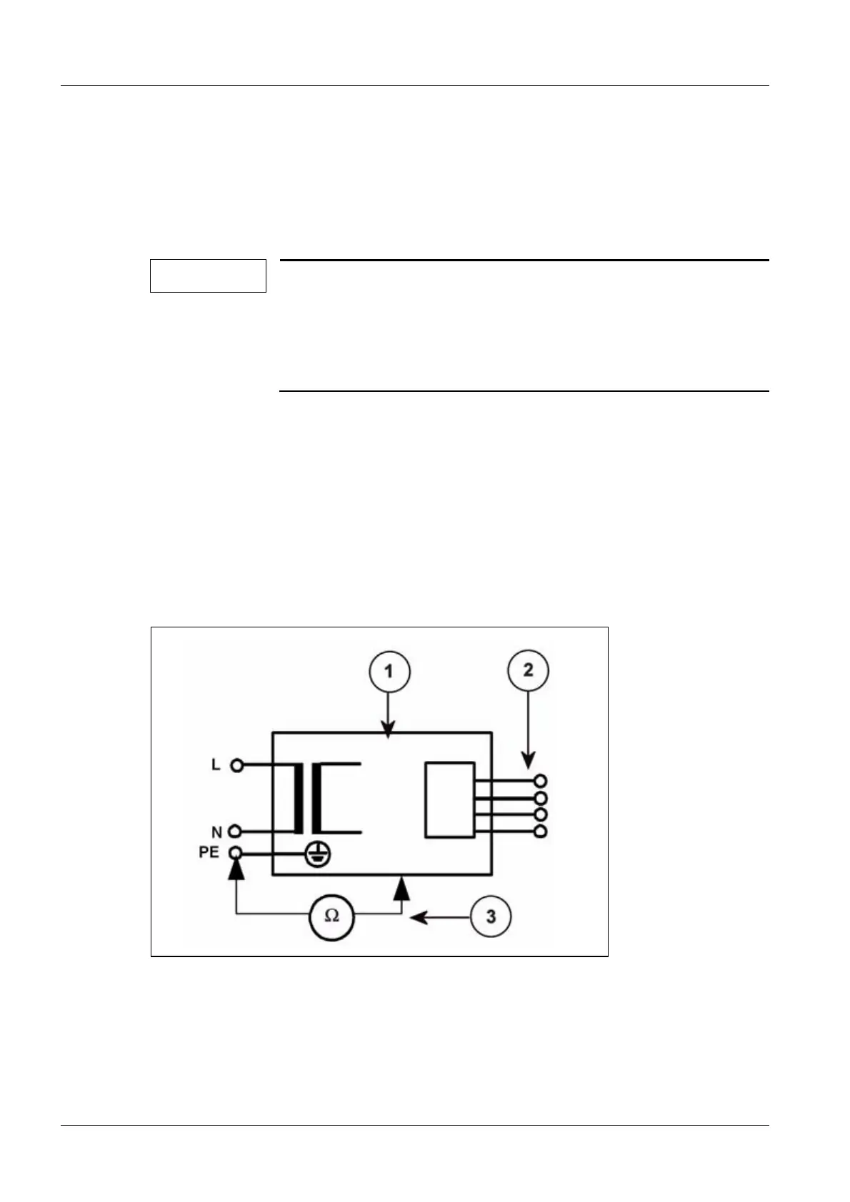
Fig. 3: Measuring circuit for measuring the protective conductor resistance for units that are
disconnected from power, in compliance with DIN VDE 0751-1/2001-10, Fig. C2.
Pos. 1 = System
Pos. 2 = Application part type B (if available)
Pos. 3 = Measurement setup (integrated into measuring device)

 Loading...