(8) Function key 1
(9) Function key 0
(10) Warning symbols
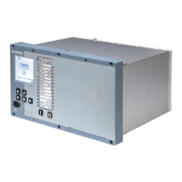
The following table gives you a detailed explanation of the function of the operator and display elements.
Operator Element/Display Element Function
Figure 4-2 LCD Display
LCD display showing menus and settings
Figure 4-3 Fascia Up Button
Menu navigation and settings increase
Figure 4-4 Fascia Down Button
Menu navigation and settings decrease
Figure 4-5 Fascia Navigation Button
Menu navigation. Binary output reset from home
screen (3 second delay). LED test/reset.
Figure 4-6 Fascia Enter Button
Enter key, used to initiate and accept settings
changes
Figure 4-7 Fascia Cancel Button
Cancel key, used to cancel settings changes and/or
move up the menu structure by one level per press
Figure 4-8 USB Port Cover
USB port to connect to other devices e.g. laptop.
Figure 4-9 Withdrawal Lever
2 levers are located on the front of the relay. They are
used to withdraw the relay from it's case.
Figure 4-10 Device Label
Label displaying the relay MLFB code and serial
number.
Using the Device Fascia
4.2 Overview of Operator Elements and Display Elements
44 Reyrolle 7SR5, Operating, Manual
C53000-B7040-C013-1, Edition 05.2021

 Loading...


