Device Connections
Arrangement of the Terminals
[dw_lwl_1k_conv_sn, 1, --_--]
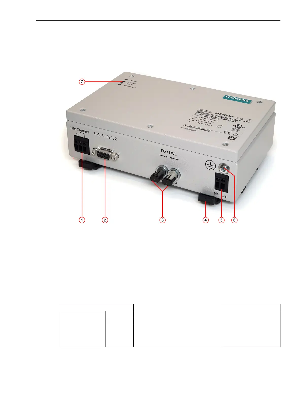
Figure 2-1
RS232 Fiber-Optic Converter
(1) Signaling-contact connector
(2) RS232 connector
(3) Fiber-optic connectors
(4) Lock bar for DIN-rail mounting
(5) Auxiliary-voltage connection
(6) Protective grounding terminal
(7) LED displays
Terminals
Connection
Description Meaning
Life contact
Pin 1 Common contact (COM) In case of a disturbance, the
contact 1-3 of the toggle
switch is closed and 1-2 is
open. When operating
correctly, 1-2 is closed and
1-3 is open.
Pin 2 Closed during normal operation
Pin 3 Closed during a disturbance
2.2
2.2.1
Device Structure
2.2 Device Connections
Accessories, RS232 Optical Fiber Converter 7XV5652-0CA00, Manual 15
C53000-G9050-C606-1, Edition 03.2020