Chapter 3
Communication Ports
RUGGEDCOM RUGGEDCOM RSG2488
Installation Guide
30 Removing an SFP Optical Port
CAUTION!
Mechanical hazard – risk of component damage. SFP optical ports are designed to insert in only
one orientation. Do not force the port into the module.
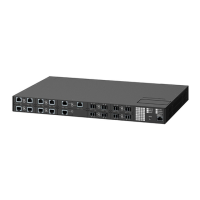
3. Remove the port from its packaging.
4. Insert the port into the module and swing the bail-latch up to lock it in place.
Figure 39: Installing an SFP Optical Port (Typical)
1. SFP Optical Port 2. Metal Bail-Latch
5. Remove the dust cover from the port.
6. Connect a cable to the port and test the connection.
Section 3.3.2
Removing an SFP Optical Port
To remove an SFP optical port, do the following:
CAUTION!
Electrical hazard – risk of damage to equipment. Make sure all electrostatic energy is dissipated before
performing installing or removing components from the device. An electrostatic discharge (ESD) can
cause serious damage to the component once it is outside the chassis.
1. Make sure all potential electrostatic build-up has been properly discharged to prevent electrostatic
discharges (ESD). This can be accomplished by wearing an ESD wrist strap or by touching Earth or the
chassis ground.
2. Disconnect the cable from the port.
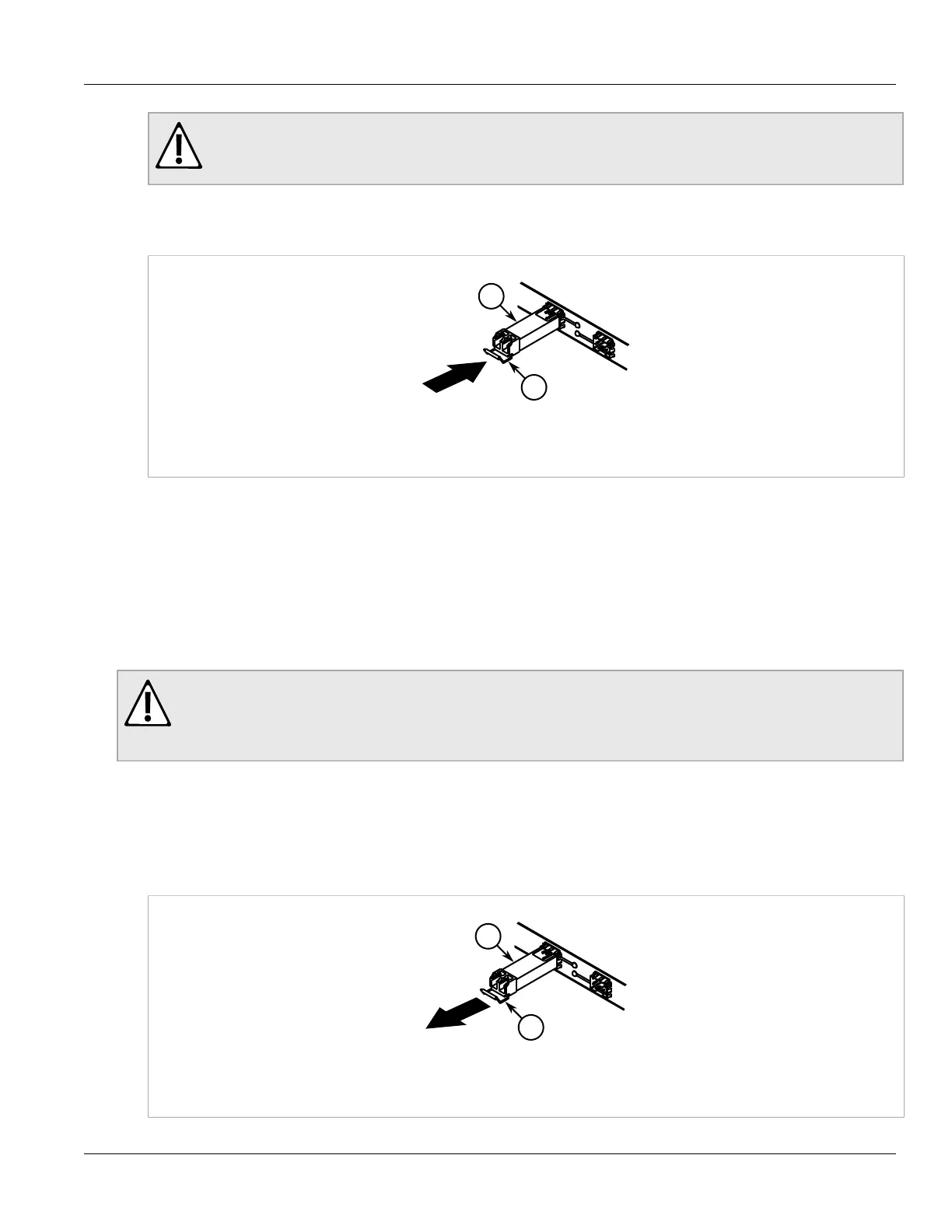
3. Grab the metal bail-latch on the port and remove the port from the module.
Figure 40: Removing an SFP Optical Port (Typical)
1. SFP Optical Port 2. Metal Bail-Latch

 Loading...