Chapter 1
Introduction
RUGGEDCOM RUGGEDCOM RSG2488
Installation Guide
2 Description
▪ Exceeds IEC 61850-3 (electric utility substations)
▪ Exceeds IEC 61000-6-2 (generic industrial)
• Supports Siemens FastConnect RJ45 Cabling System
• -40 to 85 °C (-40 to 185 °F) operating temperature (fanless)
• Conformal coated printed circuit boards (optional)
Section 1.2
Description
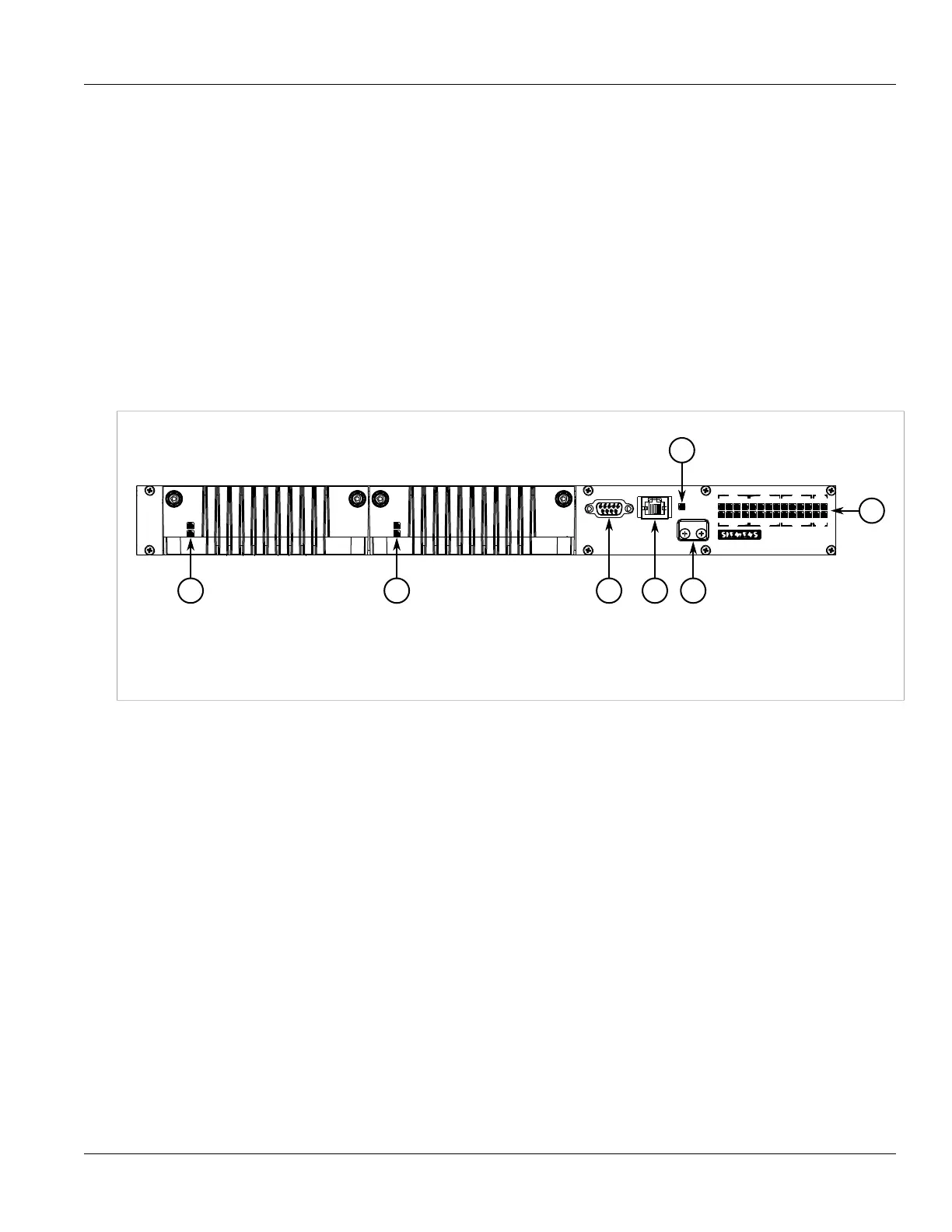
The RUGGEDCOM RSG2488 features various ports, controls and indicator LEDs on the front panel for
connecting, configuring and troubleshooting the device.
Figure 1: RUGGEDCOM RSG2488
1. Power Module Indicator LEDs 2. RS-232 Serial Console Port 3. Management Port 4. Alarm Indicator LED 5. Access Plate
6. Port Status Indicator LEDs
• Power Module Indicator LEDs – The power module indicator LEDs indicate the status of the power modules.
The top LED indicates the power supply is supplying power. The bottom LED indicates the power supply is
receiving power.
• RS-232 Console Port – The serial console port is for interfacing directly with the device and accessing initial
management functions. For information about connecting to the device via the serial console port, refer to
Section 2.7, “Connecting to the Device”.
• Management Port – The 10/100Base-T Ethernet management port is for system management that is out-of-
band from the switch fabric. For information about connecting to the device via the 10/100Base-T Ethernet
management port, refer to Section 2.7, “Connecting to the Device”.
• Alarm Indicator LED – The alarm indicator LED illuminates when an alarm condition exists.
• Access Plate – The removable access plate provides access to the microSD slot. Use a microSD card to
load/store the firmware and configuration for the device. For information about using a microSD card, refer to
Section 2.6, “Inserting/Removing the MicroSD Card”.
• Port Status Indicator LEDs – Port status indicator LEDs indicate the operational status of each port. For more
information, refer to Chapter 3, Communication Ports.

 Loading...


