RUGGEDCOM RUGGEDCOM RSG2488
Installation Guide
Chapter 3
Communication Ports
BNC Ports 31
4. Store the port in an ESD-safe bag or other suitable ESD-safe environment, free from moisture and stored at
the proper temperature (-40 to 85 °C or -40 to 185 °F).
Section 3.4
BNC Ports
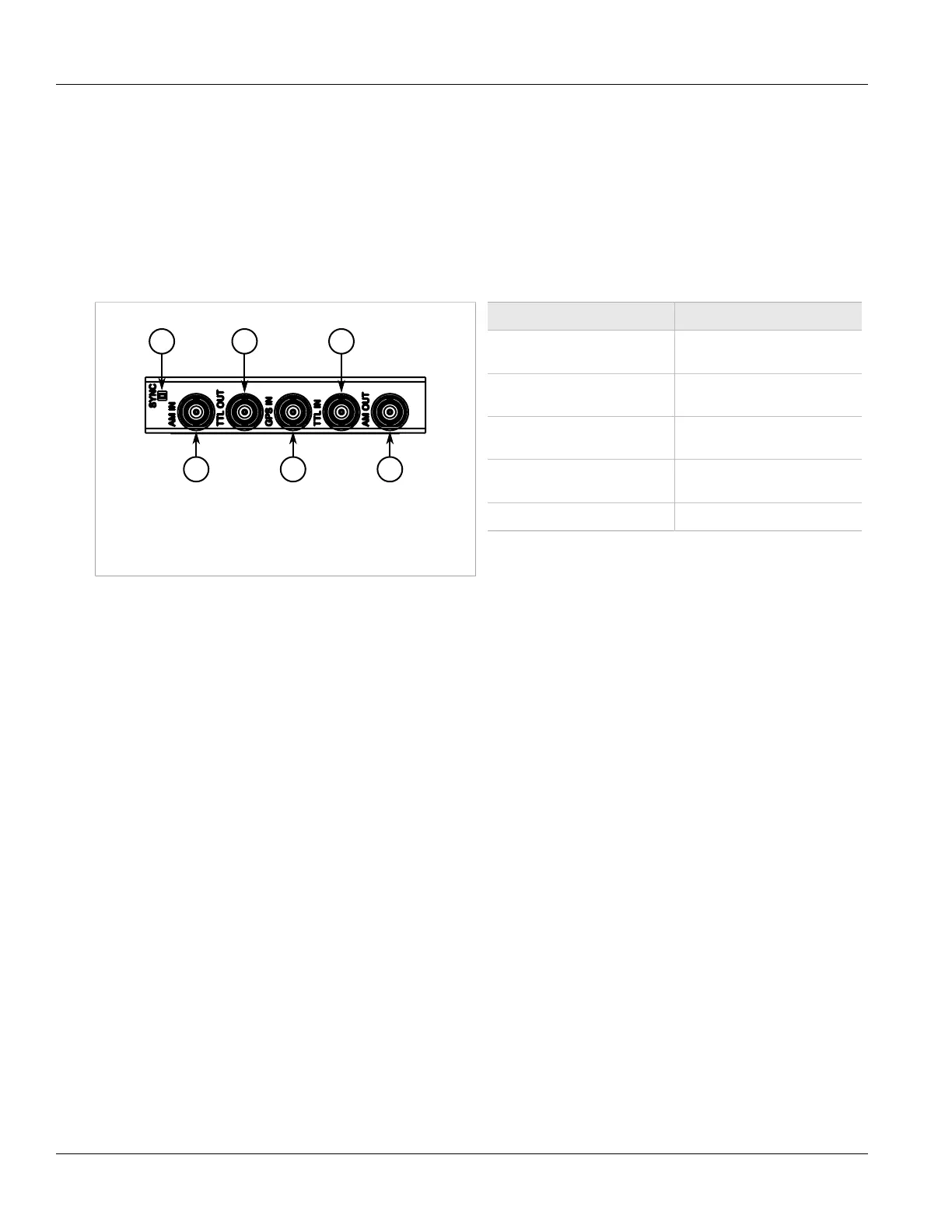
The following BNC ports are available on the PTP module:
Figure 41: PTP Module
1. Sync LED 2. AM IN Port 3. TTL OUT Port 4. GPS IN
Port 5. TTL IN Port 6. AM OUT Port
Port Function
AM IN AM-level IRIG-B signal
input, software enabled
AM OUT IRIG-B AM signal
output, software enabled
TTL OUT IRIG-B PWM or 1 PPS signal
output, software selectable
TTL IN TTL-level IRIG-
B PWM signal input
GPS IN GPS antenna input
Inputs are controlled by RUGGEDCOM ROS and only one can be active at any time. For information about
activating an input, refer to the RUGGEDCOM ROS User Guide for the RSG2488.
The color of the Sync LED on the front panel of the PTP module indicates the status of the incoming timing
signal:
• Green – Signal locked
• Amber/Yellow – Holdover
• Red – Error
• Off – No signal detected
Section 3.5
Installing/Removing Modules
The following sections describe how to install and remove modules:
• Section 3.5.1, “Installing Modules”
• Section 3.5.2, “Removing Modules”

 Loading...


