Chapter 4
Technical Specifications
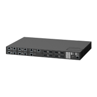
RUGGEDCOM RUGGEDCOM RSG2488
Installation Guide
38 GPS Antenna Specifications
Speed Mode
i
Connector
Type
Cable
Type
(μm)
Tx λ
(nm)
j
Tx min
(dBm)
Tx max
(dBm)
Rx
Sensitivity
(dBm)
RX
Saturation
(dBm)
Distance
(km)
j
Power
Budget
(dB)
1000Base-LX SM LC 9/125 1310 -9.5 -3 -21 -3 10 11.5
1000Base-LX SM SC 9/125 1310 -10 -3 -20 -3 10 10
1000Base-LX SM SC 9/125 1310 -5 0 -20 -3 25 15
1000Base-LX SM LC 9/125 1310 -7 -3 -24 -3 25 17
i
MM = Multi-Mode, SM = Single-Mode
j
Typical
SFP Gigabit Transceivers
Speed Mode
k
Connector
Type
Cable
Type
(μm)
Tx λ
(nm)
l
Tx min
(dBm)
Tx max
(dBm)
Rx
Sensitivity
(dBm)
RX
Saturation
(dBm)
Distance
(km)
l
Power
Budget
(dB)
50/125
1000Base-SX MM LC
62.5/125
850 -9 -2.5 -20 0 0.5 11
1000Base-LX SM LC 9/125 1310 -9.5 -3 -19 -3 10 9.5
1000Base-LX SM LC 9/125 1310 -7 -3 -23 -3 25 9.5
1000Base-LX SM LC 9/125 1550 0 5 -23 -3 70 9.5
k
MM = Multi-Mode, SM = Single-Mode
l
Typical
Section 4.5
GPS Antenna Specifications
The PTP module requires an active GPS antenna with the following specifications:
Parameter Specification
Polarization Right-Hand Circular Polarized
Receive Frequency 1.57542 GHz ± 1.023 MHz
Power Supply 5 VDC
DC Current < 10 mA at 3 VDC
Antenna Gain Select antenna gain based on system configuration
Total Gain at GPS Input Port
m
≤ 18 dBi
Axial Ratio < 3 dB
Output VSWR < 2.5
m
Includes antenna gain, cable loss, lightning arrestor loss, line amplifier gain and bandpass filter loss
NOTE
The PTP module's GPS input provides 5 VDC at up to 10 mA to power the antenna.

 Loading...