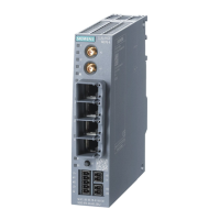
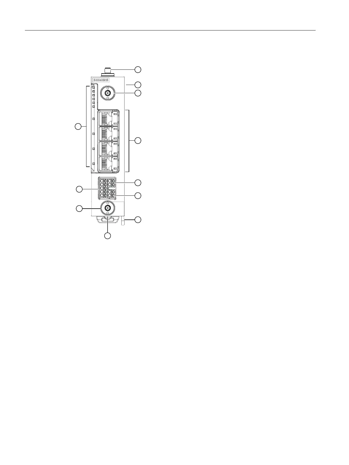
4.3 Device view
① 2 x antenna connectors A3/A4, type SMA female
② Slot for the micro SIM card 3FF on the device rear (covered)
③ Antenna connector A1, type SMA female
④ Ethernet connectors (P1, P2, P3, P4)
⑤ Digital input (DI)
⑥ Digital output (DO)
⑦ Eye for grounding (diameter 4.6mm) / wall mounting
⑧ On the bottom of the device behind the screw-on cover:
•
Reset button
• PLUG slot (CLP)
For the position, see "Reset button (Page30)".
⑨ Antenna connector A2, type SMA female
⑩ Power supply connection
⑪ LED display
Description of the device
4.3Device view
SCALANCE MUM853-1
22 Operating Instructions, 03/2023, C79000-G8976-C650-05
 Loading...