Note
Interference pulse
To avoid evaluating an interference pulse, the pulse for the signal 1 (TRUE / HIGH) must be at
least 200ms.
Wiring rules
• To wire the digital input/output, use a copper cable of category AWG18-16 or a cable with a
cross-section of 0.75 to 1.5 mm
2
.
• Always wire the digital input/output in pairs.
• The maximum permitted cable length is 30 m.
You can nd additional information in the section "Terminals (Page27)".
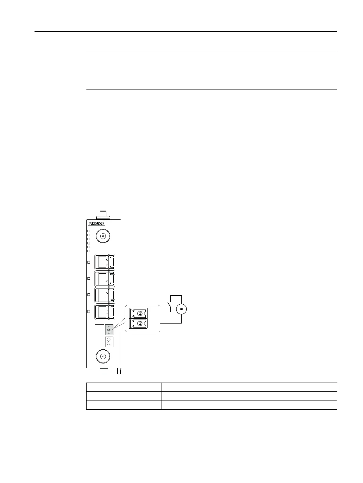
Digital input
The 2-pin terminal block has the following assignment:
Contact Assignment
+DI Input
-DI Ground
If there is an adequate switching voltage at the digital input, the digital input is active and
the "DI" LED is lit.
Connection
6.6Digital input/output
SCALANCE MUM853-1
Operating Instructions, 03/2023, C79000-G8976-C650-05 57
 Loading...