Configuration / project engineering
6.5 LED display
SCALANCE X-400
Operating Instructions, 06/2015, C79000-G8976-C186-12
125
The following table lists the significance of the three LEDs on the power module for display
modes A through C:
F off The IE Switch X-400 has not detected any faults, the sig-
naling contact is closed.
Red on The IE Switch X-400 has detected a fault, the signaling
contact opens.
L1
Power supply L1 lower than 17 V.
Power supply L1 higher than 17 V.
L2
Power supply L2 lower than 17 V.
Power supply L2 higher than 17 V.
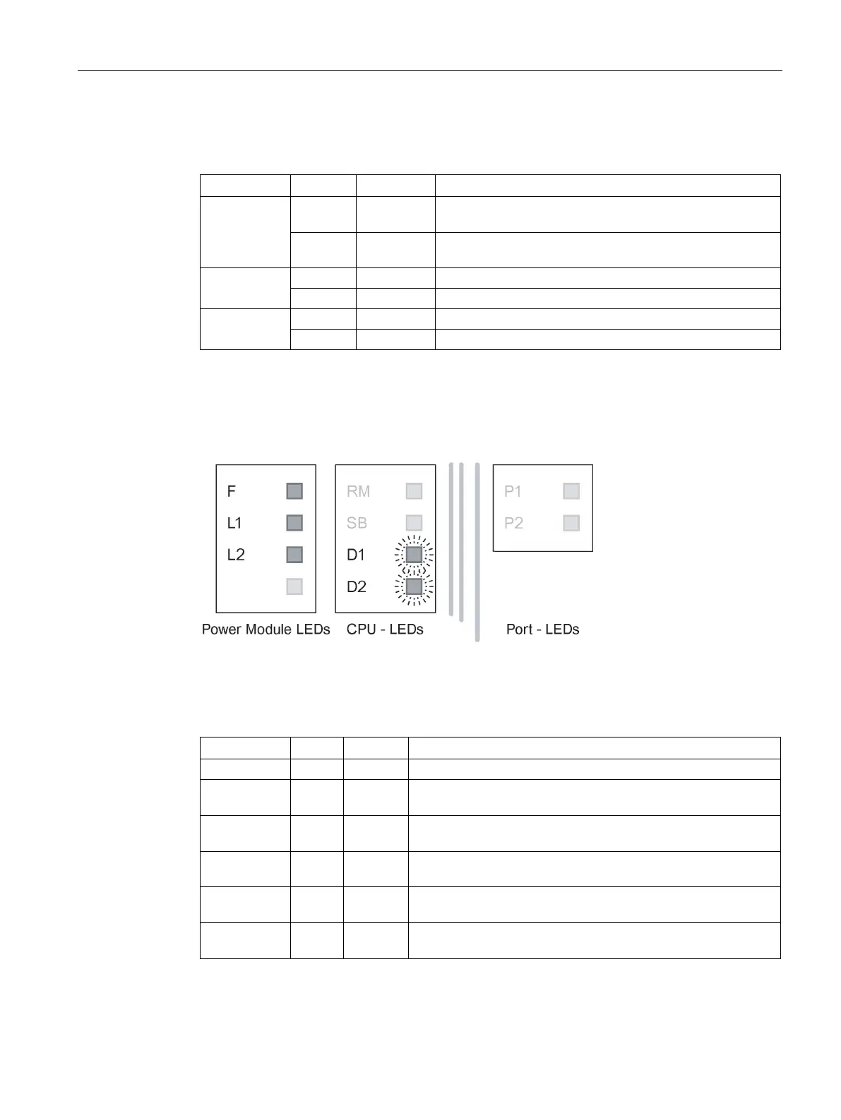
Display in display mode D
In display mode D, both the D1 and D2 LEDs of the CPU module are on. This mode
indicates whether the power supply is being monitored with the signaling contact.
Figure 6-7 LED display of the power module and the CPU module in DMode D
The following table shows the meaning of the three light emitting diodes on the power
module in display mode D:
No problem has been detected by the IE Switch X-400.
Red on The IE Switch X-400 detects a fault. The signaling contact
L1 off Power supply L1 is not monitored. If L1 falls below 17 V, the
signaling contact does not respond.
Green on Power supply L1 is monitored. If L1 falls below 17 V, the signal-
L2 off Power supply L2 is not monitored. If L2 falls below 17 V, the
signaling contact does not respond.
Green on Power supply L2 is monitored. If L2 falls below 17 V, the signal-

 Loading...


