Installation
4.2 Installing / uninstalling the SCALANCE X-400
SCALANCE X-400
Operating Instructions, 06/2015, C79000-G8976-C186-12
79
Installing / uninstalling the SCALANCE X-400
Notes on installation
IE Switches X-400 are designed for installation on an S7-300 standard rail and installation on
a 35 mm DIN rail.
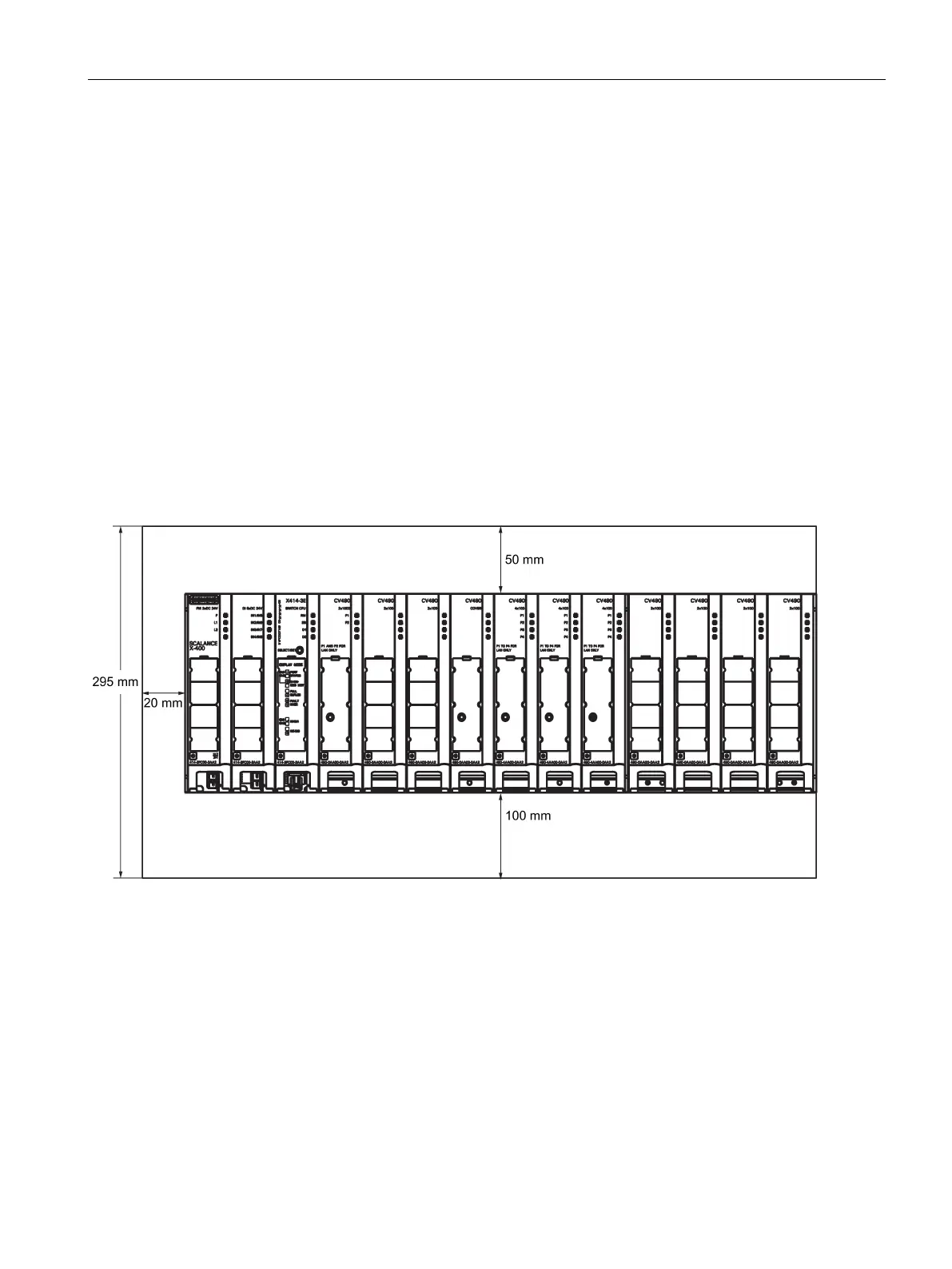
Certain minimum clearances between an IE Switch X-400 and neighboring equipment must
be taken into account. These minimum clearances are necessary during installation and
operation to allow the following:
● Install and remove modules,
● to allow the flow of air required for heat dissipation during operation of the IE Switches X-
400.
The following figure shows the space you need to allow for an IE Switch X-400.
Figure 4-1 Installation clearances for the IE Switches X-400 based on the example of a SCALANCE X414-3E with
extender module

 Loading...


