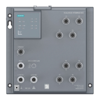
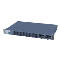
Description
3.3 System description of SCALANCE X-400
SCALANCE X-400
26 Operating Instructions, 06/2015, C79000-G8976-C186-12
due to a link-down or a device failure), the slave activates its link as long as the problem
persists. Reconfiguration takes place within 0.3 s.
-2 are used exclusively for redundant coupling of the gigabit rings, the
coupling links can also be designed with a gigabit transmission rate.
System description of SCALANCE X-400
3.3.1
Properties, functionality and features of SCALANCE X-400
This chapter explains special properties, features, and options available to you with
IE Switches X-400.
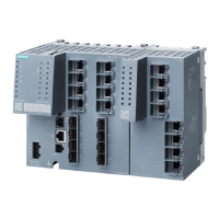
The basic device always consists of the frame, the power supply and a CPU module. The
basic device of the SCALANCE X414-3E has additional digital signal inputs.
IE Switches X-400 provide a modular structure for the required ports. The modularity
simplifies setup and subsequent expansion of complex network topologies to meet current
needs.
● Gigabit technology
The basic device has ports with a transmission rate of 1 Gbps for electrical cables
(twisted pair) or by adding gigabit media modules for fiber-optic cables (FO).
● With IE-Switches X-400, it is possible to split the ring ports on two different slots. If one of
the media modules fails, operation can be maintained as a linear bus structure. A
defective module can be replaced during operation.
● The basic device has a signaling contact for local operator control.
● There is a serial interface available for local diagnostics and local configuration.
● C-PLUG
When replacing a device, the C-PLUG can be removed and inserted in the new device so
that the configuration can be retained.
 Loading...
