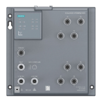
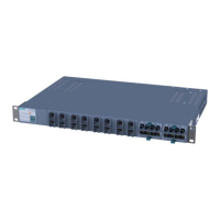
Description
3.4 Description of the product
SCALANCE X-400
38 Operating Instructions, 06/2015, C79000-G8976-C186-12
signaling contact and protective earth.
The input voltage of 24 V DC is transformed to the internal supply voltage.
● Slot 3
Digital input module
with two 5-pin sockets for connecting eight digital inputs that allow different signaling
modes.
● Slot 4
CPU module contains
– the Ethernet port, only for commissioning and configuration of the X414-3E.
– the serial RS-232 port for firmware update or management over the Command Line
Interface (CLI).
– the C-PLUG for storage of parameter assignments.
– the DIL switch for the redundancy manager function and to specify the ring ports.
– the SELECT/SET button for device display and configuration.
– the LED display for redundancy manager and standby mode as well as display modes
Dmode A through Dmode D.
● Slot 5
Contains two RJ-45 jacks allowing attachment of electrical (twisted pair) connections (10,
100, 1000 Mbps). As an option, slot 5 allows the use of an optical gigabit module with two
ports (1000Base-SX or 1000Base-LX).
● Slots 6 and 7
Optional use of two optical Fast Ethernet modules (100 Mbps) each with two ports
(100Base-FX).
● Slot 8
No function in system.
● Slot 9 through 11
Each contains four RJ-45 jacks allowing attachment of 12 electrical (twisted pair)
connections in total (10, 100 Mbps). These cannot be used by media modules.
 Loading...
