Description
3.4 Description of the product
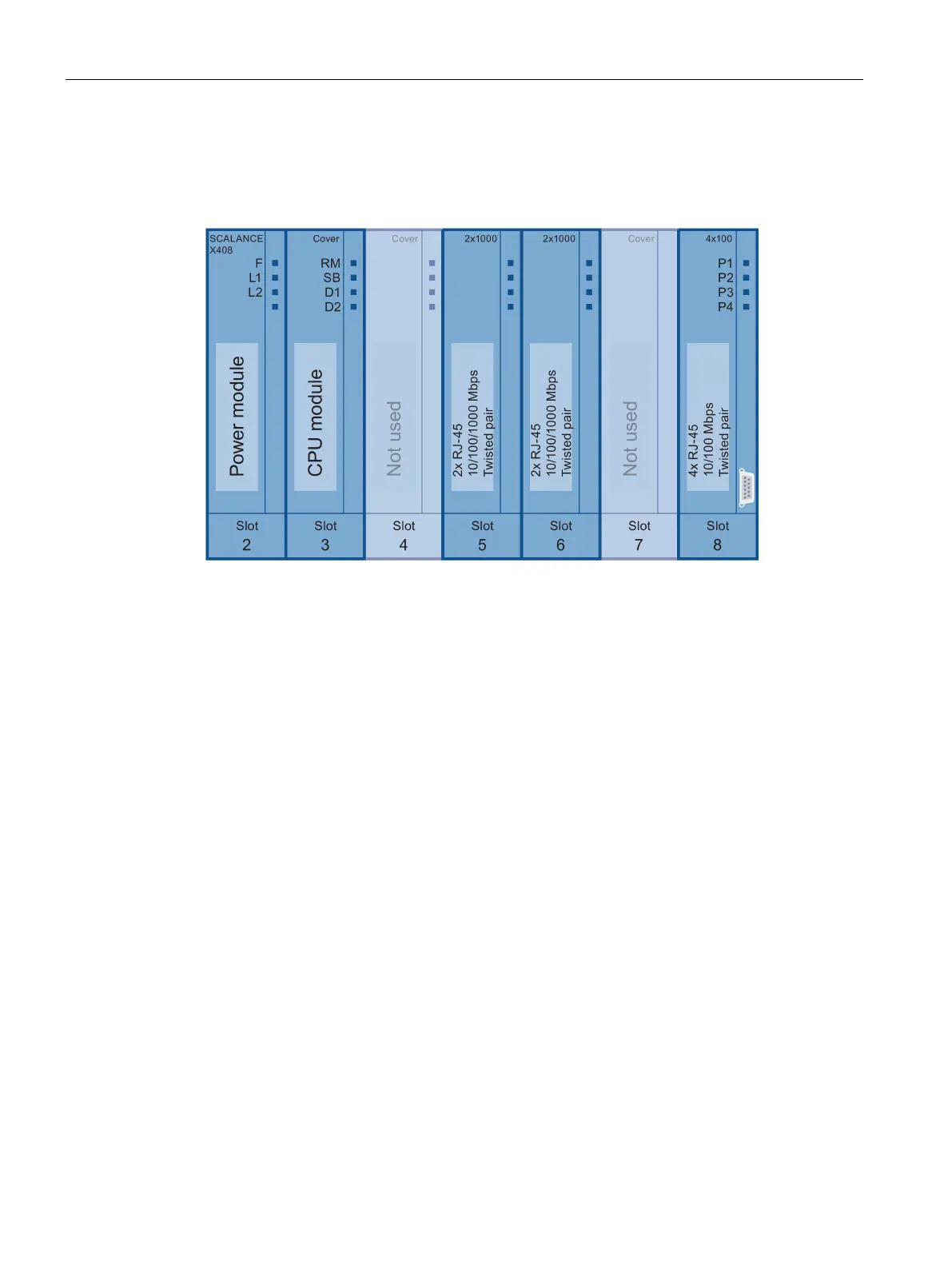
SCALANCE X-400
46 Operating Instructions, 06/2015, C79000-G8976-C186-12
The SCALANCE X408-2 basic device comprises a backplane with two fixed modules in slots
2 and 3.
Figure 3-19 Basic device X408-2 without media modules with existing ports
The modules in the individual slots have the following interfaces or control elements (slot 1 is
reserved for a power supply unit):
● Slot 2 of the
power module
– with two 4-pin sockets for connecting a redundant power supply and for connecting
the signaling contact and protective earth. The input voltage of 24 V DC is transformed
to the internal supply voltage.
– A C-PLUG for storage of parameter assignments.
– A SELECT/SET button for device display and configuration.
● Slot 3
CPU module contains
the LED display for redundancy manager and standby display as well as the display
modes DMode A through DMode D.
● Slot 4
No function in system.
● Slots 5 and 6
Both contain two RJ-45 jacks allowing attachment of electrical (twisted pair) connections
(10, 100, 1000 Mbps).
As an option (as of product version ES 04), slots 5 and 6 allow the use of any media
module (1000Base-SX or 1000Base-LX; 100Base-FX; optical gigabit module with two
ports).

 Loading...


