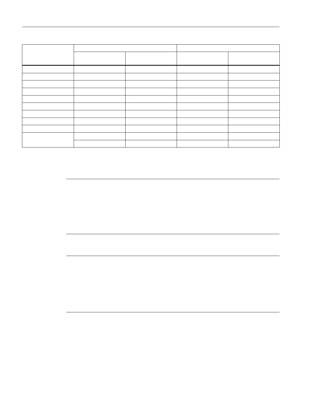
Device variant Transmitter output (optical) Receiver input
min. [dBm] max. [dBm] Sensitivity min. [dBm] Input power max.
[dBm]
X307-3 -9.5 -4 -17 -3
X307-3LD -9.5 -3 -21 -3
X308-2 -9.5 -4 -17 -3
X308-2LD -9.5 -3 -21 -3
X308-2LH -6 0 -23 -3
X308-2LH+ 0 5 -23 -3
X310 - - - -
X310FE - - - -
X320-1 FE -19 -14 -32 -3
X320-3LD FE -15
1)
-8
1)
-34
1)
-3
1)
-19
2)
-14
2)
-32
2)
-3
2)
1)
Fast Ethernet, long distance interface
2)
Fast Ethernet, multimode interface
Note
Exception in the naming of X320-3LD FE
With the X320-3LD FE IE switch, the key to the name is different. The position -3LD covers a
total of 3 connectors (1-2) of which only 2 connectors are LD, refer to the explanation below:
● Port 21: Multimode
● Port 22: LD (long distance, single mode)
● Port 23: LD (long distance, single mode)
Note
2 optical interface transceivers possible (X320-3LD FE)
The device is also equipped with 2 optical interface transceivers.
●
1)
Fast Ethernet, long distance interface
●
2)
Fast Ethernet, multimode interface
As a result, the electrical data in the technical specifications is divided into two parts:
transmitter output optical and receiver input.
Technical data
7.2 Connectors and electrical data
SCALANCE X-300
64 Compact Operating Instructions, 11/2019, A5E00982643-18
 Loading...