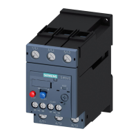
3VL IEC molded case circuit breakers
System Manual, 11/2013, 110 0110 - 02 DS 03
119
Parameter assignment / addressing
Setting the parameters
Settings on the ETU
Note
Adjusting settings
The overcurrent release is preset with the maximum settings for the overload release and
the short
-circuit release. You must adjust these settings to the requirements of the system
when installing the molded case circuit breakers.
Changing the setting values for the overload and short
-circuit releases during operation to a
value below the present operat
ing value causes instantaneous tripping.
The protection parameters to be set on the electronic trip unit of the molded case circuit
breaker depend on the technical environment (switchgear, cables), the network
configuration, and the type of equipment to be protected. There are no fixed protection
settings. The protection parameters can be determined by the relevant electrical planning
engineer.
The Siemens software tool SIMARIS Design offers a simple, quick and safe solution for
dimensioning switching and protective devices.
Internet link to SIMARIS (www.siemens.com/simaris
)
Tripping characteristic curve and settings parameters
The time/current characteristic of a trip unit offers the best method for calculating the tripping
characteristics of a trip unit. The tripping characteristic reflects the response of the circuit
breaker in the event of a fault, e.g. overload or short-circuit. The time required to trip is
defined at a specific current. The tripping characteristic is split into different sections. Each
section reflects the tripping response of the circuit breaker at a specific current level
Depending on the type of tripping, the trip units can be supplied with or without the S, N, or G
functions (L, S, I, N, G designations in accordance with IEC 60947-2, Annex K).
● L long time delay = overload protection with current-dependent long time delay and
current-dependent tripping curve (I
2
t = constant)
● S short time delay (short-circuit protection with short-time delay) = short-circuit protection
with current-dependent or current-independent short time delay and current-dependent
tripping curve (I
2
t
sd
= constant)
● I Instantaneous = short-circuit protection with instantaneous adjustable tripping.
● N Neutral protection = protection of the neutral conductor with adjustable, current-
dependent tripping curve.
● G Ground fault = ground-fault protection with current-independent short-time delay
 Loading...