Technical data
11.6 Capacitor banks
3VL IEC molded case circuit breakers
152 System Manual, 11/2013, 110 0110 - 02 DS 03
Molded case non-automatic circuit breakers
The table below shows the
power loss and the current path resistance for molded case non-
automatic circuit breakers
. The power loss applies for I
n
with 3-phase balanced load. The
specified power loss is the sum of all current paths. The current path resistance is only a
guide value and can fluctuate.
Table 11- 27 Power loss for molded case circuit breakers
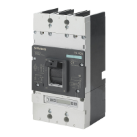
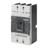
VL160X
VL160
Capacitor banks
Selection of the molded case circuit breaker for protecting and switching capacitors
This table takes account of only a few typical applications and combinations. The appropriate
selection must be made for all other applications.
Table 11- 28 Selection examples for capacitor protection circuits
Q
c
capacitor bank
power [kvar]
Capacitor rated
current
x 1.5 = I
R
of the
SENTRON VL [A]
Upstream 3VL molded case circuit breaker
230 V
400 V
415 V
525 V
50 84 VL160 80-100 1000

 Loading...


