WARNING
Structure with redundant terminal block
No terminal block (color: dark gray) may be inserted to the right of a redundant terminal block
(6DL1193-6TP00-0DF1; color black) to continue a potential group.
If this is not observed, reaction-free behavior between non-fail-safe and fail-safe modules can
no longer be guaranteed.
(FAIW-018)
Note
Terminal blocks are not included in the scope of delivery of the I/O module and must be ordered
separately.
You can nd additional information on the conguration in the system manual.
Connections on the slot and in the I/O module
4MPUPGUIF*0NPEVMF1MVHTJEFPGUIF*0NPEVMF
3
4
1
2
9
9
9
9
① Carrier module contacts of the backplane bus:
Maximum 50 mA
Maximum 3.5 V DC
② Terminal block contacts of the I/O module:
Maximum 30 V DC
Maximum 30 mA per pin / maximum 0.24 A per module
③ Process terminals on the terminal block
④ Supply voltage of the I/O module
Connection
4.1 Terminal blocks
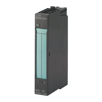
F-AI 8xI 2-/4-wire HART HA
16 Equipment Manual, 09/2021, A5E50557845-AA
 Loading...