2-10
C7-621 / C7-621 AS-i Control Systems
C79000-G7076-C621-01
Table 2-4 Pinout of the Analog Inputs/Outputs
Pin
Function
AI1-U Analog input 1, signal input for voltage
AI1-I Analog input 1, signal input for current
AI1-M Analog input 1, reference potential
AI2-U Analog input 2, signal input for voltage
AI2-I Analog input 2, signal input for current
AI2-M Analog input 2, reference potential
AI3-U Analog input 3, signal input for voltage
AI3-I Analog input 3, signal input for current
AI3-M Analog input 3, reference potential
AI4-U Analog input 4, signal input for voltage
AI4-I Analog input 4, signal input for current
AI4-M Analog input 4, reference potential
AO-U Analog output, signal output für voltage
AO-I Analog output, signal output für current
AO-M Analog output, reference potential
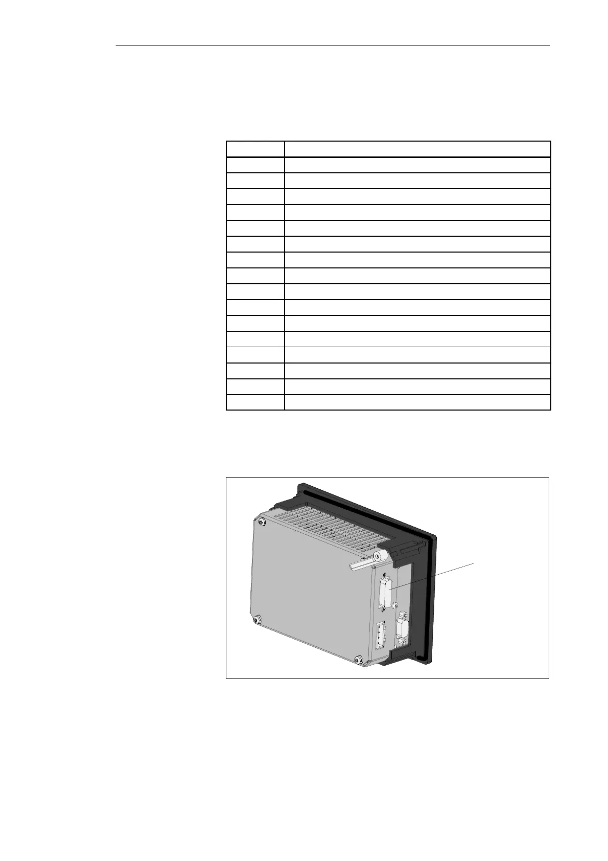
P bus connector
(IM 621)
Figure 2-9 C7-621 with IM 621 Connector
Analog Input/
Output
P Bus (IM 621)
Installing and Preparing the C7