Channel parameters
Each channel parameter block contains the cable parameters for the digital input (4 bytes).
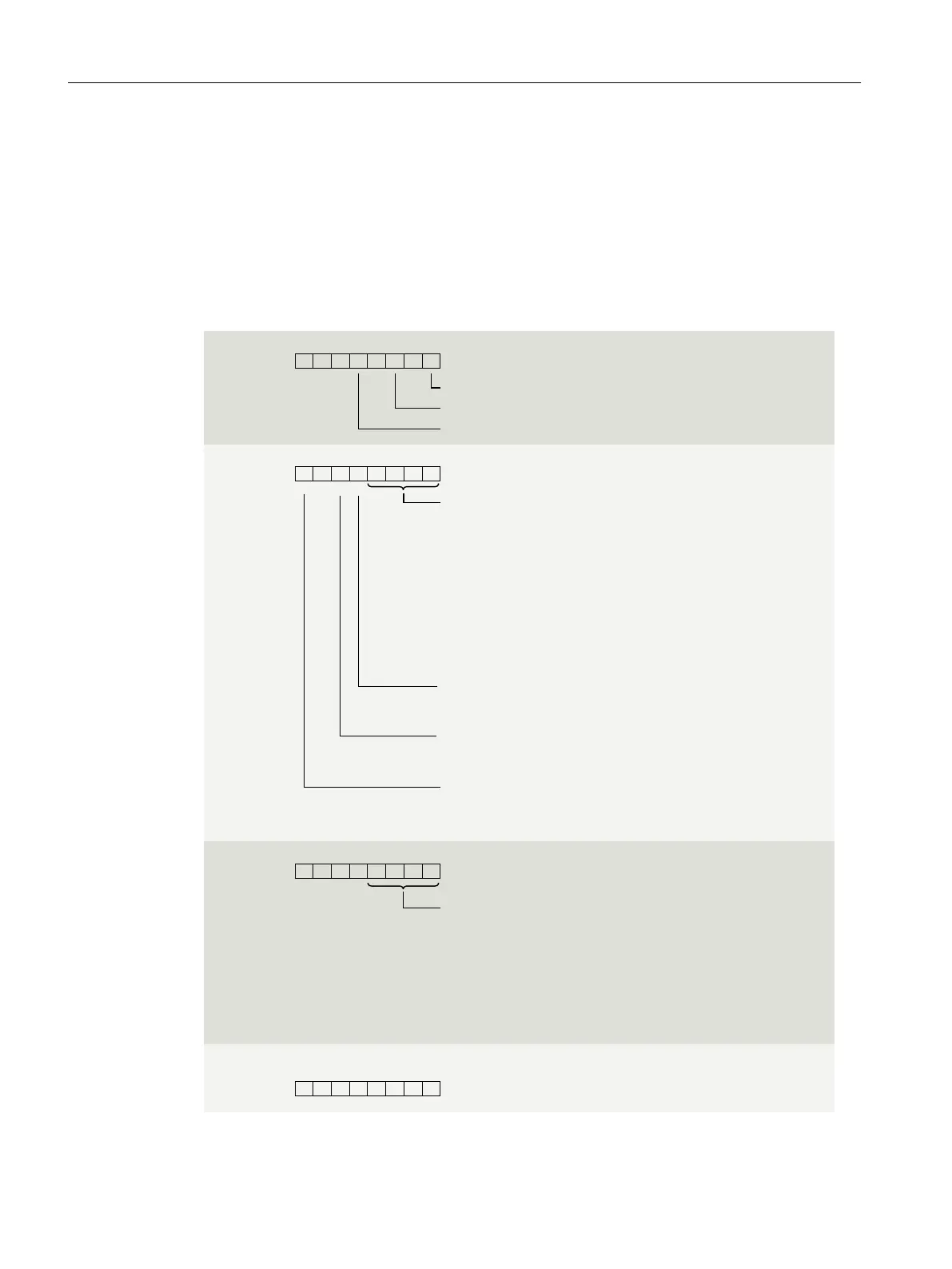
The following gure shows the conguration of the channel parameters for channels0 to 15.
x = 12 + (channel number * 4); with channel number 0…15
All unused bits and the bits or bytes marked as "reserved" must be set to zero.
You activate a channel parameter by setting the corresponding bit to "1" or the
corresponding value.
Enable diagnostics
Byte x
Byte x+1
Short-circuit to ground
Wire-break check
Input delay:
1111 = None
0000 = 0.05 ms
0001 = 0.1 ms
0011 = 0.4 ms
0100 = 0.8 ms
0110 = 3.2 ms
1001 = 12.8 ms
0101 = 1.6 ms
0000 = None
0001 = 0.5 ms
0100 = 0.05 ms
0101 = 0.1 ms
0110 = 0.2 ms
Hardware interrupt positive edge
Hardware interrupt falling edge
Wire break
Byte x+2
Pulse stretching
Reserved
Byte x+3
Channel activated
0 = blocked
1 = released
0 = blocked
1 = released
0 = blocked
1 = released
0
00 0 00
23 15 467
0 0 0
01234567
0
0 0 000
0 0 00
23 15 467
023 15 467
0
0010 = 1 s
0011 = 2 s
1010 = 20 ms
FigureA-3 Conguration byte x to x+3 for the channels 0 to 15
Drivers, parameters, diagnostics messages and address space
A.2Parameter assignment and structure of the module/channel parameters
DI 16x24VDC PA
40 Equipment Manual, 06/2023, A5E51654101-AA

 Loading...


