Mounting and connecting
3.1 Preparations
Basic Panels
Operating Instructions, 04/2012, A5E02421799-03
31
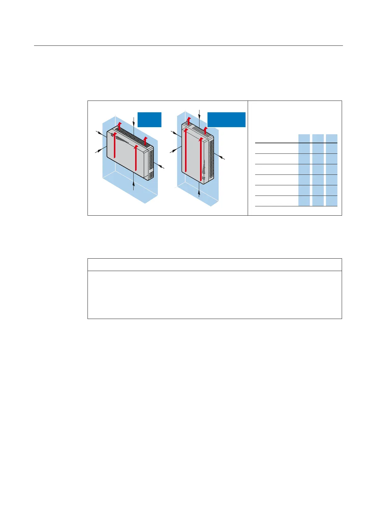
3.1.4 Checking clearances
The following clearances are required around the HMI device to ensure sufficient self-
ventilation:
y
z
x
y
x
KTP400 Basic
KTP600 Basic
All Basic
Panels
x
y
x
y
z
Required clearance around the HMI
devices.
All dimensions in mm
.73%DVLF
.73%DVLF
73%DVLF
.73%DVLF
xyz
.3%DVLF
.3%DVLF
3.1.5 Making the mounting cut-out
NOTICE
Stability of the mounting cutout
The material in the area of the mounting cutout must provide sufficient strength to
guarantee the enduring and safe mounting of the HMI device.
The force of the mounting clamps or operation of the device may not lead to deformation of
the material in order to achieve the degrees of protection described below.
Degrees of protection
The degrees of protection of the HMI device can only be guaranteed if the following
requirements are met:
● Material thickness at the mounting cutout 2 mm to 6 mm for IP65 degree of protection or
Front face only Type 4X/Type 12 (indoor use only) degree of protection. The thickness is
2 mm to 4 mm for the KP300 Basic mono PN.
● Permitted deviation from plane at the mounting cutout: ≤ 0.5 mm
This condition must be fulfilled for the mounted HMI device.
● Permissible surface roughness in the area of the seal: ≤ 120 µm (R
z
120)
A clamping frame is additionally available for the HMI device KTP1000 Basic with a material
thickness < 2 mm at the mounting cutout. The frame enables you to achieve degree of
protection IP65 or Front face only Type 4X/Type 12.