Mounting and connecting the device
3.4 Connecting the device
Unified Comfort Panels
Operating Instructions, 03/2020, A5E46641217-AA
43
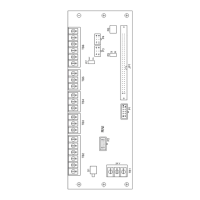
Wiring diagram
The following figure shows the connection of the equipotential bonding using the MTP1900
Unified Comfort as an example and similarly applies to the other Unified Comfort HMI
devices.
Equipotential bonding cable, 4 mm
2
Equipotential busbar for equipotential bonding cables, grounding connection and shield support
Shield of the PROFINET data cable, connected to the equipotential busbar
2

 Loading...