Service and maintenance
5.1 LED status display on the RF120C
SIMATIC RF120C
28 Operating Instructions, 02/2021, C79000-G8976-C328-03
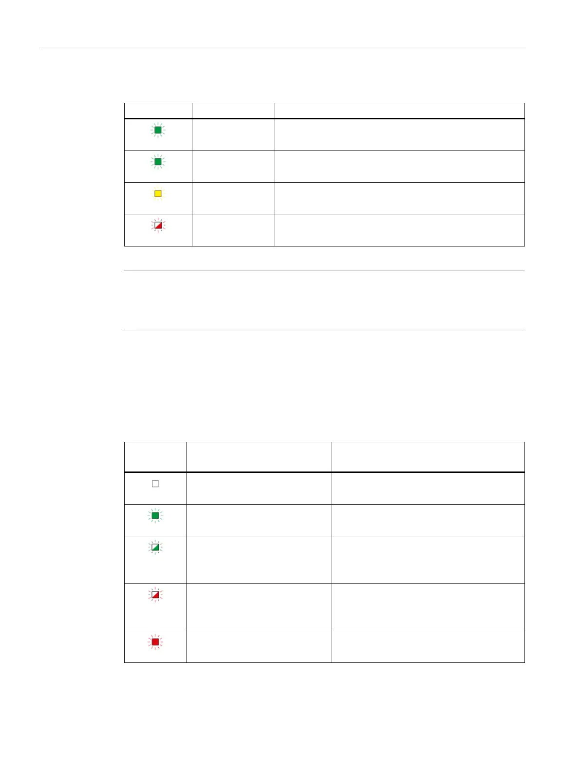
Table 5- 1 LEDs below the upper cover of the housing
Indicates that voltage is being applied via the external 24 V
power supply.
Indicates the presence of a transponder.
Indicates live communication with the reader.
A flashing pattern indicates the last error to occur. The mean-
ing of the flashing patterns is explained in the section "Error
LED colors when the module
starts up
When the module starts up, all its LEDs are lit for a short time. Multicolored LEDs display a
color mixture. At this point in time, the color of the LEDs is not clear.
Display of the operating and communication status
The LEDs indicate the operating and communications status of the module according to the
following scheme:
Table 5- 2 Display of the basic states of the module by the "DIAG" LED
DIAG
Meaning Comment
Configuration was completed successfully and
no error occurred.
flashing green
• Startup
• Module not configured
flashing red
• Defect
• Error
Check the ERROR LED and the 24 VDC LED for
more detailed error diagnostics.

 Loading...