Image processing
3.3 Options for image acquisition and image processing
SIMATIC MV500
Operating Instructions, 05/2019, C79000-G8976-C494-02
45
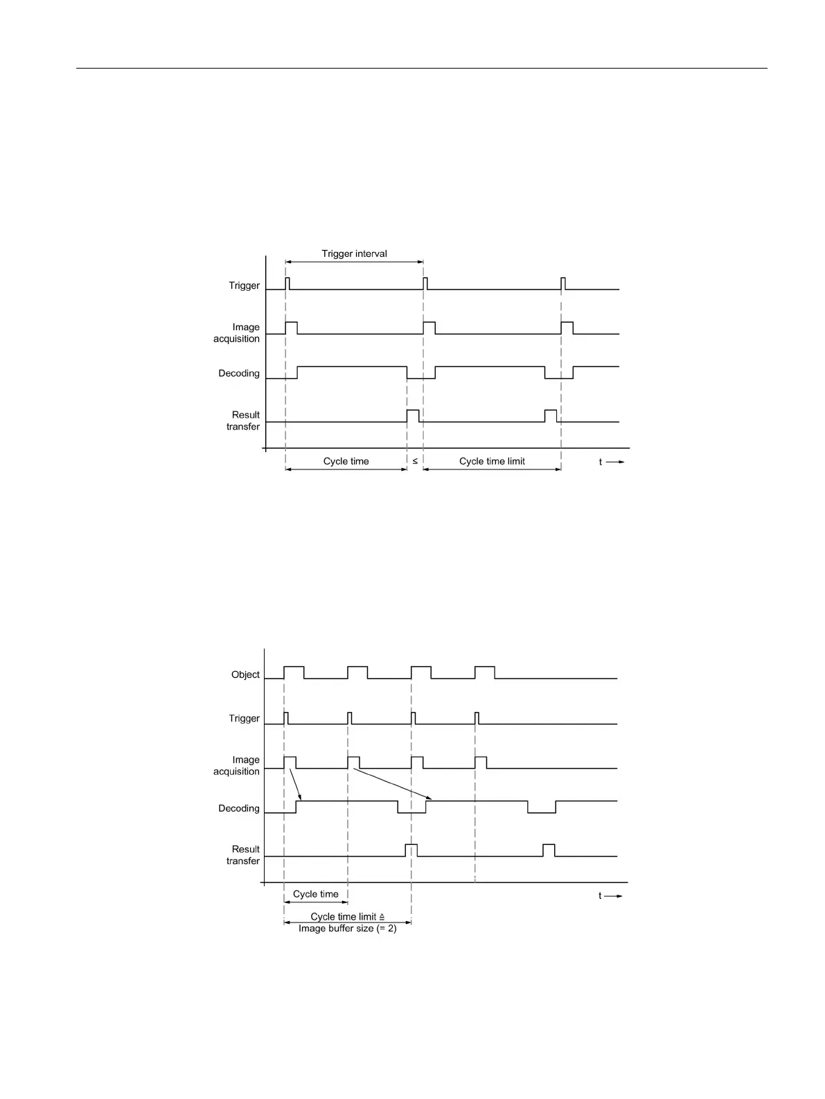
"Image buffer size = 1" setting
If the buffer size is set to the value 1, this mode corresponds to a sequential processing
chain:
Trigger → Image acquisition → Decoding/processing → Result transfer.
New triggering can be performed only when the decoding/processing has been completed.
Figure 3-4 Time diagram: Individual trigger with image buffer size = 1
"Image buffer size > 1" setting
With image buffer sizes greater than 1, intermediate buffering takes place between image
acquisition and processing and between processing and result output.
Image acquisition can at times be performed in a faster sequence and processing can also
buffer results briefly prior to transfer. This allows brief periods of peak load to be handled.
Figure 3-5 Time diagram: Individual trigger for image buffer size > 1; in the example: Image buffer
size = 2
 Loading...


