Connection
6.3 Connecting the power supply
SIMATIC MV500
Operating Instructions, 05/2019, C79000-G8976-C494-02
81
Communication module cable
You use the communication module cable to connect the communication modules (e.g.
RF180C and ASM 456) to the optical reader. The communication module cable is pre-
fabricated.
Note that when using the power supply via the communication module, you must enable the
setting "Settings > Options > Lighting > Power supply via POU or CM".
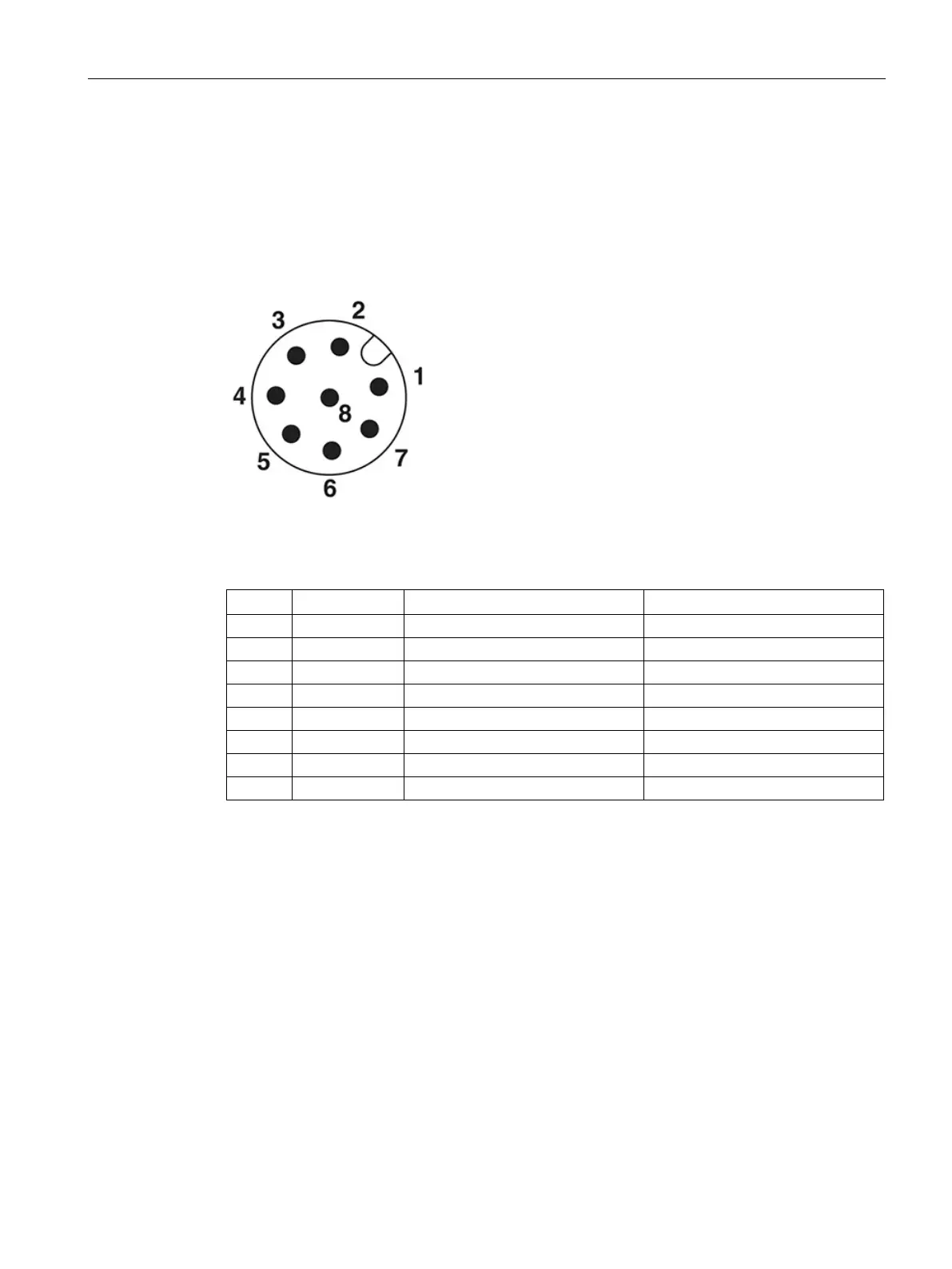
Figure 6-3 Pin assignment of communication module plug
Table 6- 2 Communication module cable, M12 (male, 8-pin) / M12 (female, 8-pin)
Pin assignment ↔ socket/wire color of the cable/signal connector of the optical reader
 Loading...


