EasyManuals Logo

Siemens SIMATIC NET S7-300 User Manual

Siemens SIMATIC NET S7-300
317 pages
To Next Page IconTo Next Page
To Previous Page IconTo Previous Page
Page #172 background imageLoading...
Page #172 background image
6 Programmed Communication Connections
A-172
S7-CPs for Industrial Ethernet Configuring and Commissioning
Release 01/2007
C79000-G8976-C182-07
6.5.2 Parameter Field for a UDP Connection
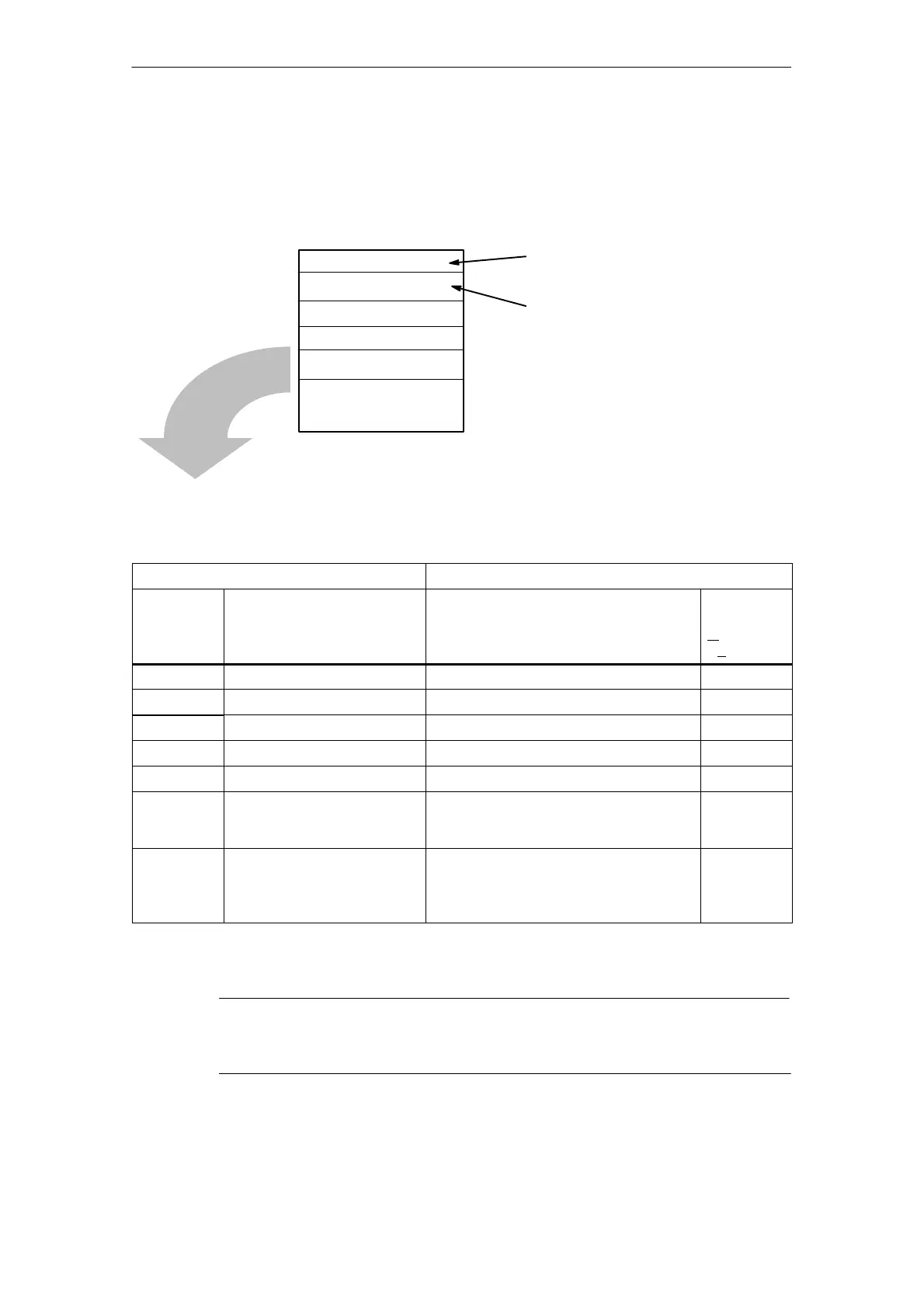
Structure
Subfield 1
Subfield n
Subfield 2
ID = connection ID
Type = 2
No_of_subfields = n
Freely assignable connection reference;
must be specified in AG_SEND / AG_RECV.
Range of values for the connection ID:
S7-400: 1,2 through 64
S7-300: 1,2 through 16
Identifier for the connection type
Usable Subfields
Table 6-6
Subfield
Parameter
ID Type
*)
Special Features / Notes
(Please refer also to the general
description in Table 6-10 Page A-177)
Use
(
mandatory /
optional)
1 SUB_IP_V4 IP address of the partner m
9 SUB_LOC_PORT - m
10 SUB_REM_PORT - m
18 SUB_CONNECT_NAME - o
19 SUB_LOC_MODE - o
21 SUB_KBUS_ADR This value is always set to 2 for CPs for
the S7-300 and does not need to be
specified.
m (for
S7-400)
23 SUB_ADDR_IN_DATABLOCK If the “Free UDP connection” is selected
for this parameter, the parameters
SUB_IP_V4, SUB_LOC_PORT,
SUB_REM_PORT are omitted.
o
*) The general properties of the subfield types are described below in Section 6.6.
Note
Please read the description of the configurable connection properties for the for
the UDP connection in Section 5.7!

Table of Contents

Other manuals for Siemens SIMATIC NET S7-300

Questions and Answers:

Question and Answer IconNeed help?

Do you have a question about the Siemens SIMATIC NET S7-300 and is the answer not in the manual?

Siemens SIMATIC NET S7-300 Specifications

General IconGeneral
Product Type DesignationSIMATIC NET S7-300
MountingDIN rail mounting
Protection ClassIP20
CPU ModelsVarious models available (e.g., CPU 312, CPU 314)
Communication InterfacesMPI, PROFIBUS DP
Power Supply24 V DC power supply required. Different power supply modules available.
I/O ModulesDigital input modules, digital output modules, analog input modules, analog output modules
ProgrammingSTEP 7 software
Supply Voltage24V DC or 120/230V AC (depending on model)
Digital InputsAvailable via digital input modules
Digital OutputsAvailable via digital output modules
Analog InputsAvailable via analog input modules
Analog OutputsAvailable via analog output modules
Communication FunctionsMPI, PROFIBUS DP, Ethernet (depending on model)
ProtocolsMPI, PROFIBUS DP, TCP/IP (depending on model)
Operating Temperature0°C to 60°C
Storage Temperature70 °C
MemoryDepends on CPU model (e.g., 32 KB to 1.5 MB)

Related product manuals