EasyManuals Logo

Siemens SIMATIC NET S7-300 User Manual

Siemens SIMATIC NET S7-300
317 pages
To Next Page IconTo Next Page
To Previous Page IconTo Previous Page
Page #79 background imageLoading...
Page #79 background image
3 Operating the Ethernet CP with
A-79
S7-CPs for Industrial Ethernet Configuring and Commissioning
Release 01/2007
C79000-G8976-C182-07
3.3.5 “Substitute Objects” in the STEP 7 Project
Overview
Communication connections can be configured fully when the communications
partners are available in the current project. For the stations on the Ethernet
subnet, whose configuration data were not created in STEP 7 or whose
configuration data are not managed in the currently active project, the following
substitute objects can be created in the project:
SIMATIC S5 stations
PG/PC
Other stations
- for devices of other manufacturers
- for SIMATIC S7 stations in another project (not necessary in a multiproject)
Note
Instead of creating substitute objects, you can also configure unspecified
connections for connections to the stations listed above.
In the Properties dialog of these connections, you must then specify the full
partner address. These partners do not appear in the NetPro plant view.
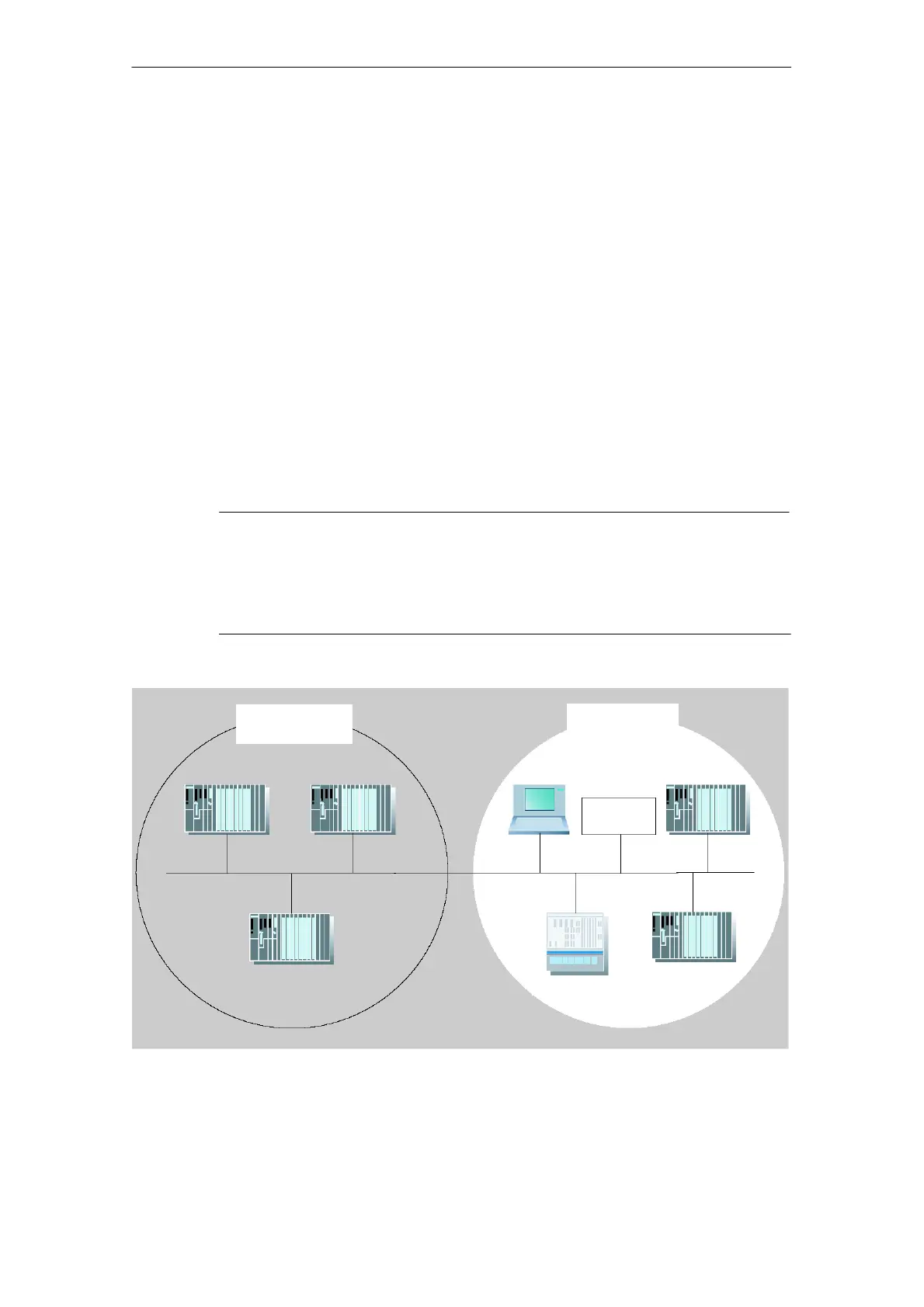
Ethernet subnet (1)
Plant
”Production 1”
SIMATIC S5
Third-party
device
S7-400/1
S7-400/5
Plant
”Production 2”
S7-400/2 S7-400/4
S7-400/3
PC/PG

Table of Contents

Other manuals for Siemens SIMATIC NET S7-300

Questions and Answers:

Question and Answer IconNeed help?

Do you have a question about the Siemens SIMATIC NET S7-300 and is the answer not in the manual?

Siemens SIMATIC NET S7-300 Specifications

General IconGeneral
Product Type DesignationSIMATIC NET S7-300
MountingDIN rail mounting
Protection ClassIP20
CPU ModelsVarious models available (e.g., CPU 312, CPU 314)
Communication InterfacesMPI, PROFIBUS DP
Power Supply24 V DC power supply required. Different power supply modules available.
I/O ModulesDigital input modules, digital output modules, analog input modules, analog output modules
ProgrammingSTEP 7 software
Supply Voltage24V DC or 120/230V AC (depending on model)
Digital InputsAvailable via digital input modules
Digital OutputsAvailable via digital output modules
Analog InputsAvailable via analog input modules
Analog OutputsAvailable via analog output modules
Communication FunctionsMPI, PROFIBUS DP, Ethernet (depending on model)
ProtocolsMPI, PROFIBUS DP, TCP/IP (depending on model)
Operating Temperature0°C to 60°C
Storage Temperature70 °C
MemoryDepends on CPU model (e.g., 32 KB to 1.5 MB)

Related product manuals