EasyManuals Logo

Siemens SIMATIC NET S7-300 User Manual

Siemens SIMATIC NET S7-300
317 pages
To Next Page IconTo Next Page
To Previous Page IconTo Previous Page
Page #193 background imageLoading...
Page #193 background image
7 Programming FCs (Functions) and FBs for S7 Ethernet CPs
A-193
S7-CPs for Industrial Ethernet Configuring and Commissioning
Release 01/2007
C79000-G8976-C182-07
7.3.1 FC5 AG_SEND / FC50 AG_LSEND
Meaning of the Block
The FCs AG_SEND / AG_LSEND pass data to the Ethernet CP for transfer over a
configured connection.
The selected data area can be a memory bit area or a data block area.
Error-free execution of the function is indicated when the entire user data area
could be sent over Ethernet.
The way in which the FC functions depends on the CP type you are using. Please
note the differences in the following section.
Note:
Unless otherwise stated, all the following information applies to both the FCs
AG_SEND and AG_LSEND.
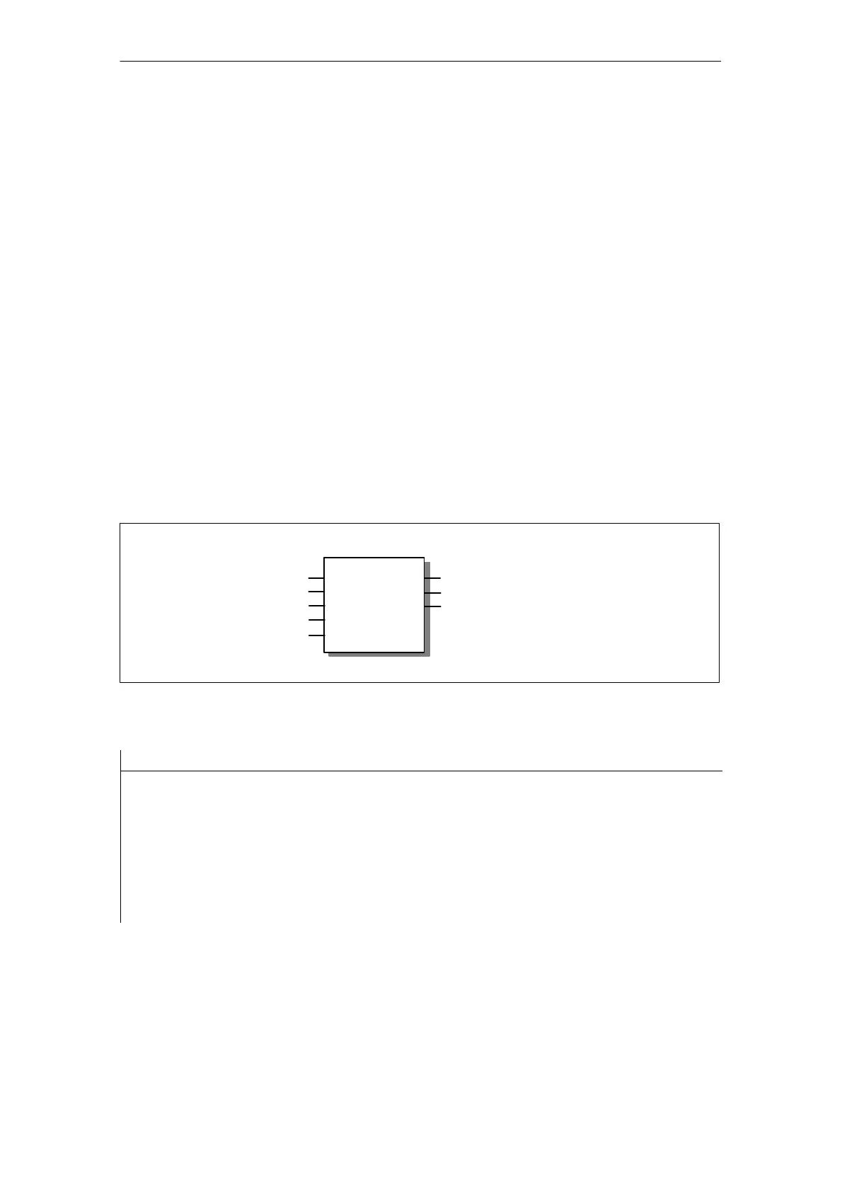
Call
Call interface in FBD representation
ACT
LADDR
DONE
AG_SEND / AG_LSEND
ID
SEND
LEN
ERROR
STATUS
BOOL
INT
WORD
ANY
INT
WORD
BOOL
BOOL
Example in STL representation
STL Explanation
call fc 5
ACT := M 10.0
ID := MW 12
LADDR := W#16#0100
SEND := P#db99.dbx10.0 byte 240
LEN := MW 14
DONE := M 10.1
ERROR := M 10.2
STATUS := MW 16
//AG_SEND / AG_LSEND block call
//Job triggered by memory bit
//Connection ID acc. to configuration
//=LADDR 256 dec. in hw configuration
//Buffer with send data
//Length for send data
//Execution code
//Error code
//Status code

Table of Contents

Other manuals for Siemens SIMATIC NET S7-300

Questions and Answers:

Question and Answer IconNeed help?

Do you have a question about the Siemens SIMATIC NET S7-300 and is the answer not in the manual?

Siemens SIMATIC NET S7-300 Specifications

General IconGeneral
Product Type DesignationSIMATIC NET S7-300
MountingDIN rail mounting
Protection ClassIP20
CPU ModelsVarious models available (e.g., CPU 312, CPU 314)
Communication InterfacesMPI, PROFIBUS DP
Power Supply24 V DC power supply required. Different power supply modules available.
I/O ModulesDigital input modules, digital output modules, analog input modules, analog output modules
ProgrammingSTEP 7 software
Supply Voltage24V DC or 120/230V AC (depending on model)
Digital InputsAvailable via digital input modules
Digital OutputsAvailable via digital output modules
Analog InputsAvailable via analog input modules
Analog OutputsAvailable via analog output modules
Communication FunctionsMPI, PROFIBUS DP, Ethernet (depending on model)
ProtocolsMPI, PROFIBUS DP, TCP/IP (depending on model)
Operating Temperature0°C to 60°C
Storage Temperature70 °C
MemoryDepends on CPU model (e.g., 32 KB to 1.5 MB)

Related product manuals