EasyManuals Logo

Siemens SIMATIC NET S7-300 User Manual

Siemens SIMATIC NET S7-300
317 pages
To Next Page IconTo Next Page
To Previous Page IconTo Previous Page
Page #216 background imageLoading...
Page #216 background image
7 Programming FCs (Functions) and FBs for S7 Ethernet CPs
A-216
S7-CPs for Industrial Ethernet Configuring and Commissioning
Release 01/2007
C79000-G8976-C182-07
How the Block Works
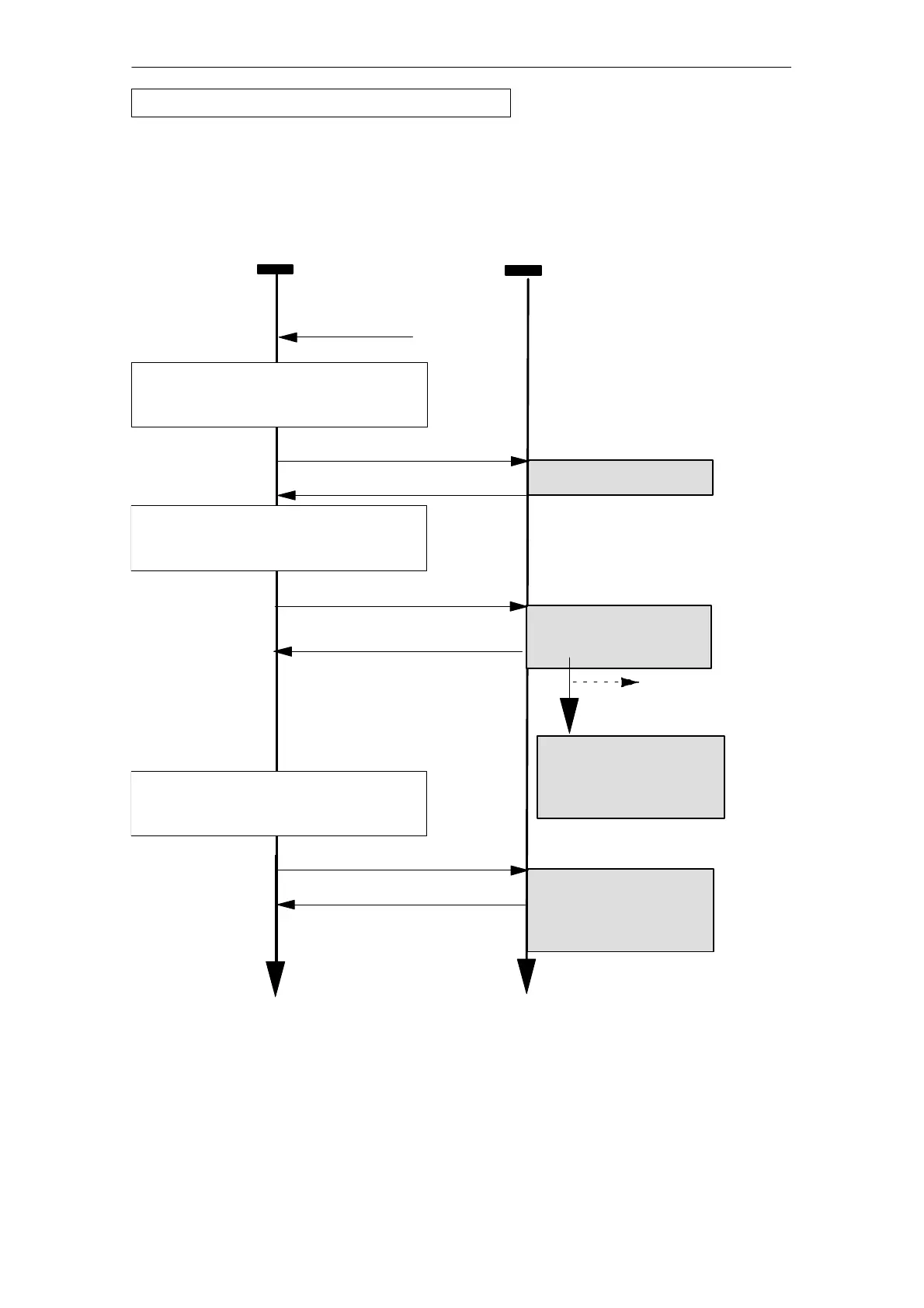
The following diagram shows a typical sequence of AG_CNTRL jobs in the user
program.
User program
(CPU cycle)
Ethernet CP
AG_CNTRL (status query)
Status connection ID1
1)
supply AG_CNTRL for status query:
ACT = 1; CMD=1
ID =1 (connection)
Status query for connection
1 is acknowledged
Legend:
1)
Parameter transfer DONE, ERROR, STATUS and RESULT1/2
Time
Time
An event is detected that makes it
useful to abort and reestablish a
connection.
AG_CNTRL (reset command)
supply AG_CNTRL for reset:
ACT = 1; CMD=2
ID =1 (connection)
Reset request active:
Reset ID (bit 15 in
RESULT1) is set
Acknowledgment of job
acceptance:
RESULT1: “connection
establishment triggered”
1)
Connection is terminated
and reinitialized:
Reset ID (bit 15 in
RESULT1) remains set
AG_CNTRL (status query)
Status connection ID1
1)
supply AG_CNTRL for status query:
ACT = 1; CMD=1
ID =1 (connection)
Status query is
acknowledged;
then the reset ID (bit 15 in
RESULT1) is cleared
Acknowledgment:
RESULT1: B095
H
“Reset was executed”
1)
Entry in diagnostic
buffer
The diagram shows how the connection status is initially queried and then, in a
second job, how the connection termination is triggered with the reset command.
FC10 AG_CNTRL - continued

Table of Contents

Other manuals for Siemens SIMATIC NET S7-300

Questions and Answers:

Question and Answer IconNeed help?

Do you have a question about the Siemens SIMATIC NET S7-300 and is the answer not in the manual?

Siemens SIMATIC NET S7-300 Specifications

General IconGeneral
Product Type DesignationSIMATIC NET S7-300
MountingDIN rail mounting
Protection ClassIP20
CPU ModelsVarious models available (e.g., CPU 312, CPU 314)
Communication InterfacesMPI, PROFIBUS DP
Power Supply24 V DC power supply required. Different power supply modules available.
I/O ModulesDigital input modules, digital output modules, analog input modules, analog output modules
ProgrammingSTEP 7 software
Supply Voltage24V DC or 120/230V AC (depending on model)
Digital InputsAvailable via digital input modules
Digital OutputsAvailable via digital output modules
Analog InputsAvailable via analog input modules
Analog OutputsAvailable via analog output modules
Communication FunctionsMPI, PROFIBUS DP, Ethernet (depending on model)
ProtocolsMPI, PROFIBUS DP, TCP/IP (depending on model)
Operating Temperature0°C to 60°C
Storage Temperature70 °C
MemoryDepends on CPU model (e.g., 32 KB to 1.5 MB)

Related product manuals