EasyManuals Logo

Siemens SIMATIC NET S7-300 User Manual

Siemens SIMATIC NET S7-300
317 pages
To Next Page IconTo Next Page
To Previous Page IconTo Previous Page
Page #250 background imageLoading...
Page #250 background image
7 Programming FCs (Functions) and FBs for S7 Ethernet CPs
A-250
S7-CPs for Industrial Ethernet Configuring and Commissioning
Release 01/2007
C79000-G8976-C182-07
Example
In a normal situation (depending on the total length of the IO data), the block will
run over several user program cycles until the condition code DONE/NDR = 1 is
signaled.
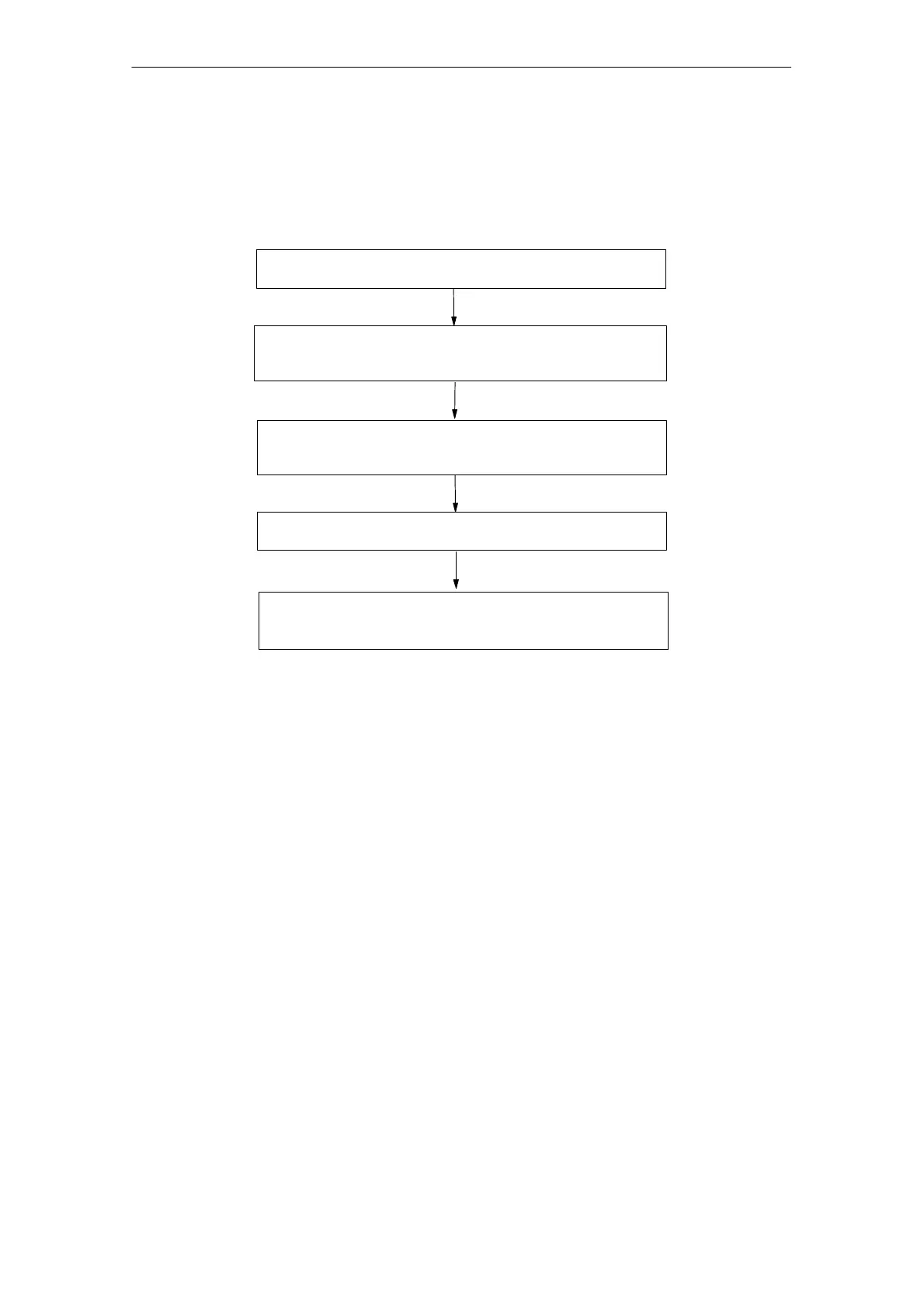
Call the PNIO_RECV block until NDR = 1
Check the IOPS status of the received data (from the
PNIO devices) and, if necessary, start error handling
Edit and process data, prepare new output data
Call the PNIO_SEND block until DONE = 1
Check the IOCS status values received from the PNIO
devices and, if necessary, start error handling
Note: The user program cycle and the cycle of the IO data exchange between the
PNIO controller and PNIO devices are independent of each other.
7.8.5 Substitute Values
The setting of substitute values is supported for the two following operational
situations:
Substitute values during startup (operating mode change on the CPU from
STOP to RUN
Substitute values if problems are detected (remove/insert or station
failure/return)
Substitute Values during Startup
You can initialize the outputs with substitute values by setting a memory bit
(“start-up” memory bit) in the start-up OB. In cyclic mode (OB1), evaluate this
“start-up” memory bit to call the PNIO_SEND block with the initialization values
when appropriate.

Table of Contents

Other manuals for Siemens SIMATIC NET S7-300

Questions and Answers:

Question and Answer IconNeed help?

Do you have a question about the Siemens SIMATIC NET S7-300 and is the answer not in the manual?

Siemens SIMATIC NET S7-300 Specifications

General IconGeneral
Product Type DesignationSIMATIC NET S7-300
MountingDIN rail mounting
Protection ClassIP20
CPU ModelsVarious models available (e.g., CPU 312, CPU 314)
Communication InterfacesMPI, PROFIBUS DP
Power Supply24 V DC power supply required. Different power supply modules available.
I/O ModulesDigital input modules, digital output modules, analog input modules, analog output modules
ProgrammingSTEP 7 software
Supply Voltage24V DC or 120/230V AC (depending on model)
Digital InputsAvailable via digital input modules
Digital OutputsAvailable via digital output modules
Analog InputsAvailable via analog input modules
Analog OutputsAvailable via analog output modules
Communication FunctionsMPI, PROFIBUS DP, Ethernet (depending on model)
ProtocolsMPI, PROFIBUS DP, TCP/IP (depending on model)
Operating Temperature0°C to 60°C
Storage Temperature70 °C
MemoryDepends on CPU model (e.g., 32 KB to 1.5 MB)

Related product manuals