EasyManuals Logo

Siemens SIMATIC NET S7-300 User Manual

Siemens SIMATIC NET S7-300
317 pages
To Next Page IconTo Next Page
To Previous Page IconTo Previous Page
Page #266 background imageLoading...
Page #266 background image
8 NCM S7 Diagnostics
A-266
S7-CPs for Industrial Ethernet Configuring and Commissioning
Release 01/2007
C79000-G8976-C182-07
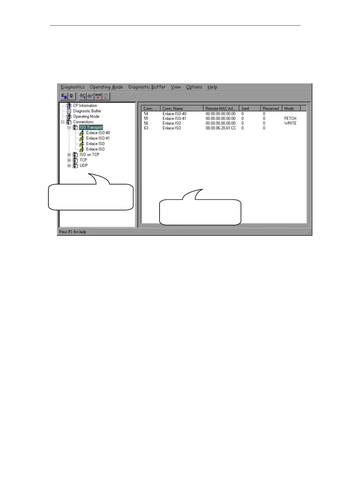
Structure
In the same way, for example, as the SIMATIC Manager, NCM S7 Diagnostics
appears as a separate two-part application window with a menu and toolbar:
Navigation area with
diagnostic objects
Content area with the
diagnostic result
In the navigation area on the left-hand side, you will find the hierarchically
arranged diagnostic objects.
You have an overview of the available diagnostic functions at all times. The
object structure displayed in the navigation area is adapted to the type of CP
you are currently checking and the functions and connections configured for the
CP.
In the content area, on the right-hand side, you will see the result of the
diagnostic function you selected in the navigation area.
Operation
By selecting a diagnostic object in the navigation area with the mouse, you
execute the diagnostic function.
Using the menu bar and toolbar, you control the sequence of the diagnostics
with context-sensitive menu commands.

Table of Contents

Other manuals for Siemens SIMATIC NET S7-300

Questions and Answers:

Question and Answer IconNeed help?

Do you have a question about the Siemens SIMATIC NET S7-300 and is the answer not in the manual?

Siemens SIMATIC NET S7-300 Specifications

General IconGeneral
Product Type DesignationSIMATIC NET S7-300
MountingDIN rail mounting
Protection ClassIP20
CPU ModelsVarious models available (e.g., CPU 312, CPU 314)
Communication InterfacesMPI, PROFIBUS DP
Power Supply24 V DC power supply required. Different power supply modules available.
I/O ModulesDigital input modules, digital output modules, analog input modules, analog output modules
ProgrammingSTEP 7 software
Supply Voltage24V DC or 120/230V AC (depending on model)
Digital InputsAvailable via digital input modules
Digital OutputsAvailable via digital output modules
Analog InputsAvailable via analog input modules
Analog OutputsAvailable via analog output modules
Communication FunctionsMPI, PROFIBUS DP, Ethernet (depending on model)
ProtocolsMPI, PROFIBUS DP, TCP/IP (depending on model)
Operating Temperature0°C to 60°C
Storage Temperature70 °C
MemoryDepends on CPU model (e.g., 32 KB to 1.5 MB)

Related product manuals