4 SEND/RECEIVE Interface in the User Program
A-93
S7-CPs for Industrial Ethernet Configuring and Commissioning
Release 01/2007
C79000-G8976-C182-07
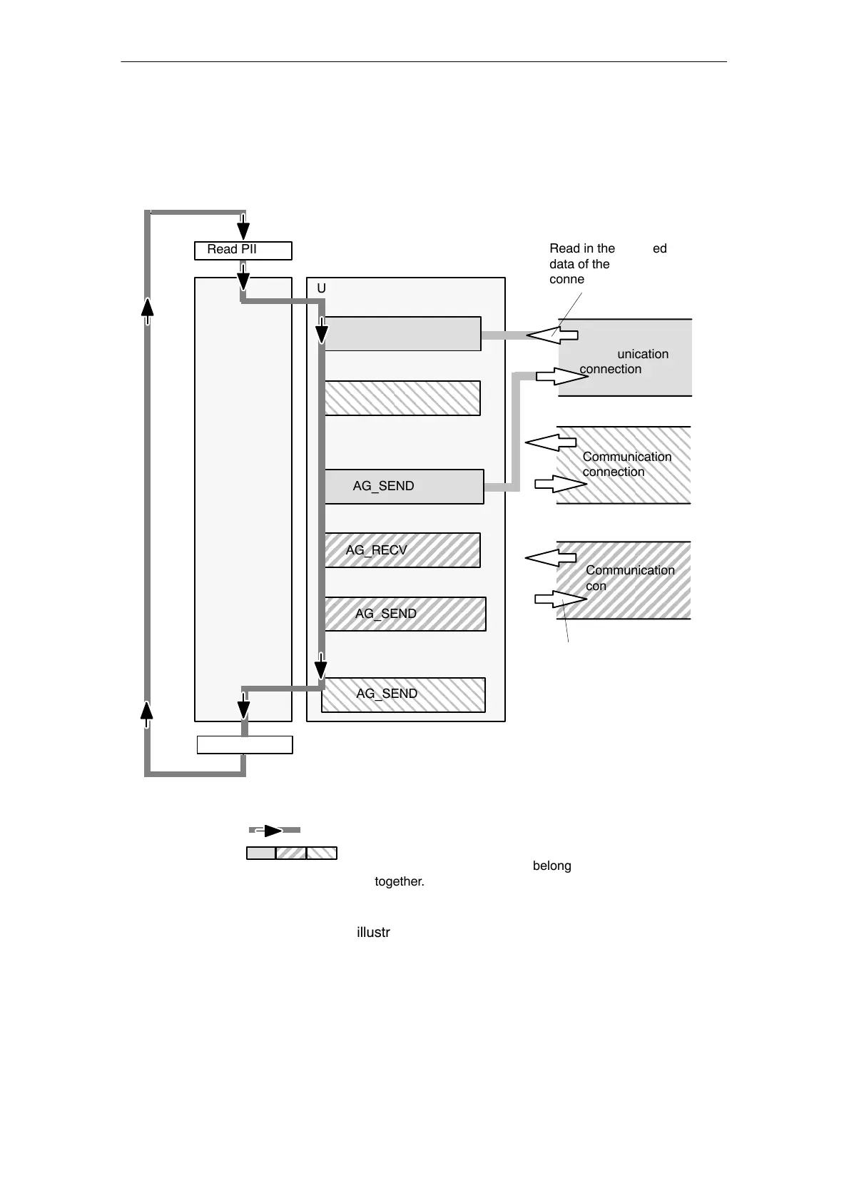
Calling FCs in the CPU Program
One possible sequence for FCs in conjunction with the organization and program
blocks in the CPU cycle is illustrated in the following diagram.
AG_RECV
AG_SEND
AG_SEND
Read in the received
data of the
connection
Transfer send data
for the connection
Write PIQ
OB
ÇÇÇÇÇÇÇÇÇ
ÇÇÇÇÇÇÇÇÇ
ÇÇÇÇÇÇÇÇÇ
Legend:
Sequence of the CPU cycle
AG_RECV
AG_RECV
Communication
connection
ÇÇÇÇÇÇÇ
ÇÇÇÇÇÇÇ
ÇÇÇÇÇÇÇ
ÇÇÇÇÇÇÇ
ÍÍÍÍÍÍÍ
ÍÍÍÍÍÍÍ
ÍÍÍÍÍÍÍ
ÍÍÍÍÍÍÍ
ÍÍÍÍÍÍÍ
AG_SEND
User program
The different shading shows which
connections and FC blocks belong
together.
Read PII
Communication
connection
Communication
connection
Figure 4-2 Typical Sequence of Function Calls in the CPU Cycle
The following points are illustrated by the diagram:
The user program consisting of any number of blocks (OBs, FBs or FCs -> see
also /6/ accesses several connections (Figure 4-2 illustrates three connections).

 Loading...


