Application planning
4.5 Mounting cut-out
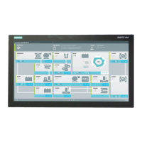
SIMATIC Panel PC 877
4-10 Operating instructions, Release 07/2006, A5E00877780-01
Table 4-1 Dimensions for the mounting cut-out in mm
Control unit L1 L2 L3
1)
L4
1)
L5 L6
2)
L7
2)
L8
2)
L9
2)
A1 A2 S1 S2
S3
S4
S5
3)
S6
3)
S7
3)
Tolerance +1 +1 ±0.2 ±0.5 ±0.5 ±0.5 ±0.5 +1 ±1 ±1 ±1 ±1 ±1 ±1
Key panel
12" TFT
15" TFT
450
450
290
321
465
465
235
279
112
112
—
186
—
135
—
25
—
165
16
16
10
17
78
51
78
51
56
56
—
—
Touch panel
15" TFT
19" TFT
450
450
290
380
465
465
235
235
112
112
—
—
—
—
—
—
—
—
16
16
10
10
81
46
81
46
56
—
—
33
1)
M6 thread or drilled holes of 7 mm diameter
2)
Cut-outs for the slots or inserted labels are required for 15'' key panels only
3)
Two clamps are required vertically for clamp mounting for the 19' touch panels only
Preparing the mounting cut-out
Steps for preparing the mounting cut-out
1 Select a location suitable for mounting, taking into account the mounting position.
2 On the basis of the dimension diagrams, check whether the required screw and pressure points
on the rear and the seal area are easily accessible after the completion of the mounting cut-out.
Otherwise the mounting cut-out is useless.
3 Complete the mounting cut-out in accordance with the dimensions.