3.2 Editing the symbols in HW Config
3.2.1 How to edit the symbols of the analog input module
Introduction
To allocate names to the addresses of the "AI8x12Bit" analog input module, assign symbolic
names and comments for each address in the "Edit symbols" dialog.
Requirements
● The analog input module is configured in HW Config.
● HW Config is open.
Procedure
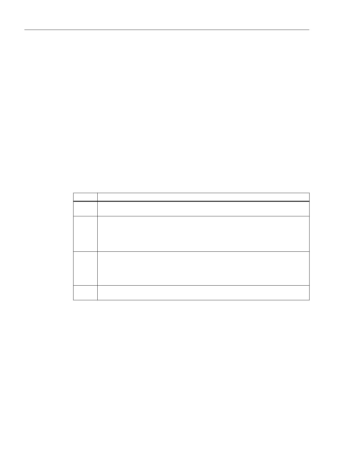
Step Action
1 In the configuration table, open the shortcut menu of the analog input module in slot 4 and
select the menu command Edit symbols....
2 In the "Symbol" column, enter "PIDCTRL1-PV_IN" for the first address (EW 512) and use
the tab key to move the mouse pointer to the "Data type" column and further to the "Com‐
ment" column. In the "Comment" column, re-enter the symbolic name from the "Symbol"
column.
Tip: Copy the name entered in the "Symbol" column and paste it into the "Comment" column.
3 Enter the symbolic names and comments for the remaining addresses in the same manner.
● Second address (EW 514): "PIDCTRL2-PV_IN"
● Third address (EW 516): "PIDCTRL1-LMNR_IN"
● Fourth address (EW 520): "PIDCTRL2-LMNR_IN"
4 Click "OK".
Your settings are applied and the dialog box closes.
Configuring the hardware and networks
3.2 Editing the symbols in HW Config
Getting Started (V8.1 with APL)
16 Getting Started, 07/2014, A5E32713210-AA
 Loading...


